Radio Broadcast cannot be Received or Poor Reception
Circuit diagnosis
INSPECTION PROCEDURE
| 1. CHECK RADIO RECEIVER |

Check the radio's automatic station search function.
Move the vehicle to a location where radio wave reception is possible.
Check the radio's automatic station search function by activating it.
- OK:
- The radio's automatic station search function works properly.
|
|
||||

| NG | |
 |
| 2. INSPECT RADIO RECEIVER |
Disconnect the radio receiver connector J66.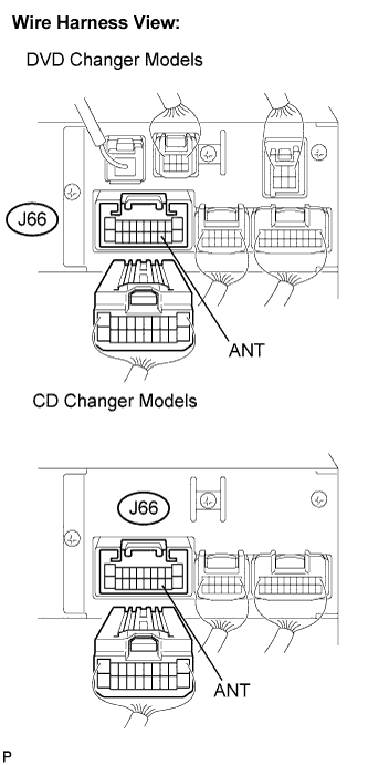

Measure the voltage according to the value(s) in the table below.
- Standard voltage:
Tester connection
Condition
Specified condition
ANT - Body ground
Engine SW on (IG),
Radio SW ON
10 to 14 V
|
|
||||
| OK | |
|
| 3. CHECK OPTIONAL COMPONENTS |
Check optional components (sun-shade film, telephone antenna, etc.).
Check if any optional components, such as sun-shade film or telephone antenna that may decrease reception capacity, are installed.
- OK:
- Optional components are installed.
- NOTICE:
- Do not remove any optional components installed by the customer without his or her consent.
|
|
||||
| NG | |
|
| 4. CHECK RADIO RECEIVER |
Preparation for check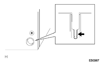
Remove the antenna plug from the radio receiver.
Check for noise
Turn the engine switch on (ACC) with the radio receiver connector connected.
Turn the radio on and put into AM mode.
Place a screwdriver, thin wire, or other metal object on the radio receiver's antenna jack and check that noise can be heard from the speaker.
- OK:
- Noise occurs.
|
|
||||
| OK | |
|
| 5. CHECK GLASS ANTENNA |
Check for continuity of the antenna.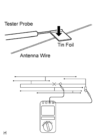
- HINT:
- Check for continuity at the center of each antenna wire as shown in the illustration.
- NOTICE:
- When cleaning the glass, wipe it in the direction of the wire with a soft dry cloth. Take care not to damage the wire. Do not use detergents or glass cleaners with abrasive ingredients. When measuring voltage, wrap a piece of tin foil around the tip of the negative probe and press the foil against the wire with your finger, as shown in the illustration.
- OK:
- There is continuity in the antenna.
|
|
||||
| OK | |
|
| 6. CHECK ANTENNA CORD |
Remove the antenna plug of the radio receiver and antenna.
Measure the resistance between the antenna cord's inner conductor and radio receiver to check for an open circuit in the antenna cord.
- Standard resistance:
- Below 1 Ω
Measure the resistance between the antenna cord's inner conductor and body ground to check for a short circuit in the antenna cord.
- Standard resistance:
- 10 kΩ or higher
|
|
||||
| OK | |
|
| 7. REPLACE AMPLIFIER ANTENNA |
Replace the amplifier antenna and check if radio broadcasts can be received normally.
- OK:
- Radio broadcasts can be received.
|
|
||||
| NG | ||
 |
||
| ||