Entire Combination Meter does not Operate
Circuit diagnosis
DESCRIPTION
- This circuit is the power source circuit for the meter.
- This circuit provides two types of power sources; one is a constant power source mainly used as a backup power source, and the other is a power source mainly used for signal transmission. The constant power source is mainly used as a backup power source of the meter CPU, however, it is also used for communication.
- If a voltage of 12 V is not applied to terminal IG+ when the engine switch is on (IG), the indicator will not operate.
WIRING DIAGRAM
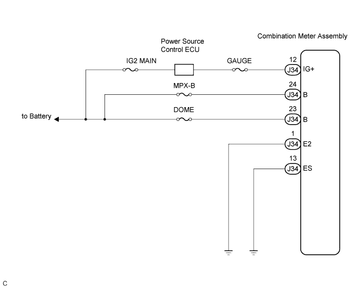

INSPECTION PROCEDURE
| 1. INSPECT COMBINATION METER ASSEMBLY |

Disconnect the J34 connector.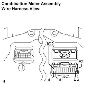
Measure the resistance according to the value(s) in the table below.
- Standard resistance:
Tester Connection
Condition
Specified Condition
J34-1 (E2) -
Body ground
Always
Below 1 Ω
C34-13 (ES) -
Body ground
Always
Below 1 Ω
Measure the voltage according to the value(s) in the table below.
- Standard voltage:
Tester Connection
Condition
Specified Condition
J34-12 (IG+) -
Body ground
Engine switch on (IG)
10 to 14V
J34-23 (B) -
Body ground
Always
10 to 14 V
J34-24 (B) -
Body ground
Always
10 to 14 V
|
|
||||

| OK | ||
 |
||
| ||