Fuel Receiver Gauge Malfunction
Circuit diagnosis
DESCRIPTION
- The meter CPU receives fuel level signals from this circuit. The fuel sender controls the resistance value in accordance with changes in sender gauge position. The meter CPU detects the fuel level from the transformed voltage. The meter CPU outputs a constant voltage of 12 V to the fuel sender. In the fuel sender, the voltage is changed due to the resistance. The changed voltage is output from the fuel sender to the meter CPU, thus the fuel level is determined by fuel injection signals transmitted using the BEAN lines.
WIRING DIAGRAM
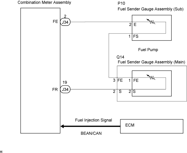

INSPECTION PROCEDURE
| 1. CHECK CAN COMMUNICATION SYSTEM |

Check if CAN communication DTC is output (Click here(for LHD), Click here (for RHD)).
- Result:
Result
Proceed to
DTC is not output
A
DTC is output
B
|
|
||||

| A | |
 |
| 2. CHECK MULTIPLEX COMMUNICATION SYSTEM |
Check if MULTIPLEX communication DTC is output (Click here).
- Result:
Result
Proceed to
DTC is not output
A
DTC is output
B
|
|
||||
| A | |
|
| 3. PERFORM ACTIVE TEST BY INTELLIGENT TESTER |
Connect the intelligent tester to the DLC3.
Engine switch on (IG).
Turn the tester ON.
Enter following menus: Diagnosis / Body / Combination Meter / Active Test.
Check the values by referring to the table below.
Combination Meter: Item
Test Details
Diagnostic Note
Fuel Meter Operation
EMPTY, 1/2, FULL
-
- OK:
- Needle indication is normal.
|
|
||||
| OK | |
|
| 4. READ VALUE OF INTELLIGENT TESTER |
Connect the intelligent tester to the DLC3.
Engine switch on (IG).
Turn the tester ON.
Enter following menus: Diagnosis / Body / Combination Meter / Data Test.
Check the values by referring to the table below.
Combination Meter: Item
Measurement Item/Range (Display)
Normal Condition
Diagnostic Note
Fuel Input
Fuel input signal Min.: 0, Max.: 255
Fuel gauge indicates (F): 47
Fuel gauge indicates (1/2): 148
Fuel gauge indicates (E): 205
-
- OK:
- Fuel value signal displayed on the tester is almost the same as needle indication.
|
|
||||

| OK | ||
 |
||
| ||
| 5. INSPECT FUEL SENDER GAUGE ASSEMBLY |
Disconnect the connectors from the fuel sender gauges.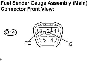
Measure the resistance according to the value(s) in the table below.
- Standard resistance::
- Fuel sender gauge (Main):
Tester Connection
Condition
Specified Condition
Q14-2 (S) - Q14-3 (FE)
Always
6.5 to 242.6 Ω
- Fuel sender gauge (Sub):
Tester Connection
Condition
Specified Condition
P10-1 (FS) - P10-2 (E)
Always
6.5 to 171.9 Ω
|
|
||||
| OK | |
|
| 6. CHECK HARNESS AND CONNECTOR (COMBINATION METER ASSEMBLY - FUEL SENDER GAUGE ASSEMBLY) |
Disconnect the fuel tank wires from the fuel sender gauge assembly.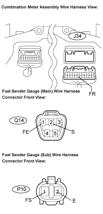
Measure the resistance according to the value(s) in the table below.
- Standard resistance:
Tester Connection
Condition
Specified Condition
J34-19 (FR) - Q14-2 (S)
Always
Below 1 Ω
Q14-3 (FE) - P10-1(FS)
Always
Below 1 Ω
P10-2 (E) - J34-2 (FE)
Always
Below 1 Ω
Q14-2 (S) - Body ground
Always
10 kΩ or higher
P10-1 (FS) - Body ground
Always
10 kΩ or higher
J34-2 (FE) - Body ground
Always
10 kΩ or higher
|
|
||||
| OK | |
|
| 7. INSPECT FUEL SENDER GAUGE ASSEMBLY |
Disconnect the fuel sender gauge connector.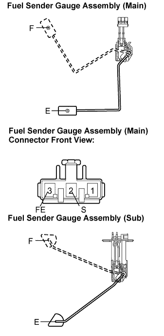
Inspect the fuel sender gauge assembly (main).
Remove the fuel sender gauge assembly (main).
Check that the float moves smoothly between F and E.
Measure the resistance between the terminals 2 (S) and 3 (FE) of connector according to the value(s) in the table below.
- Standard resistance:
- Main:
Float Level
Resistance (Ω)
F
6.5 to 8.5
Between E and F
6.5 to 242.6 (Gradually changes)
E
237.6 to 242.6
Inspect the fuel sender gauge assembly (sub).
Remove the fuel sender gauge assembly (sub).
Check that the float moves smoothly between F and E.
Measure the resistance between the terminals 1 (FS) and 2 (E) according to the value(s) in the table below.
- Standard resistance:
- Sub:
Float Level
Resistance (Ω)
F
6.5 to 8.5
Between E and F
6.5 to 171.9 (Gradually changes)
E
167.9 to 171.9
|
|
||||
| OK | |
|
| 8. REPLACE COMBINATION METER ASSEMBLY |
Replace the combination meter assembly to a new one or a known normal one.
- OK:
- The operation of the combination meter assembly returns to normal.
|
|
||||
| OK | ||
|
||
| ||