Mute Signal Circuit between Radio Receiver and Stereo Component Amplifier
Circuit diagnosis
DESCRIPTION
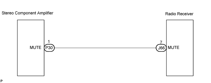
This circuit sends a signal to the stereo component amplifier to mute noise. Because of that, the noise produced by changing the sound source ceases.If there is an open in the circuit, noise can be heard from the speakers when changing the sound source.
If there is a short in the circuit, even though the stereo component amplifier is normal, no sound, or only an extremely small sound, can be produced.
WIRING DIAGRAM

INSPECTION PROCEDURE
| 1. INSPECT STEREO COMPONENT AMPLIFIER |

Measure the voltage according to the value(s) in the table below.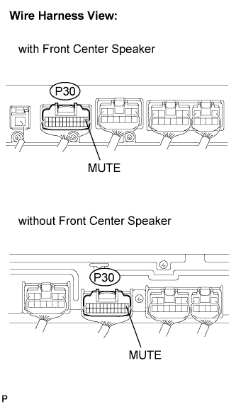
- Standard voltage:
Tester connection
Condition
Specified condition
MUTE - Body ground
Turn engine switch on (ACC), Audio system is playing → Changing
Above 3.5 V → Below 1 V
|
|
||||

| NG | |
 |
| 2. CHECK HARNESS AND CONNECTOR (RADIO RECEIVER - STEREO COMPONENT AMPLIFIER) |
Disconnect the radio receiver connector J66 and stereo component amplifier connector P30.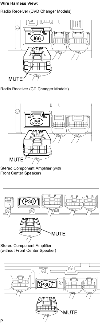
Measure the resistance according to the values in the table below.
- Standard resistance:
Tester connection
Condition
Specified condition
MUTE - MUTE
Always
Below 1 Ω
MUTE - Body ground
Always
10 kΩ or higher
|
|
||||
| OK | |
|
| 3. INSPECT STEREO COMPONENT AMPLIFIER |
Reconnect the stereo component amplifier connector P30.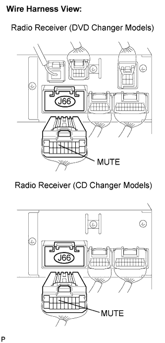
Measure the voltage according to the value(s) in the table below.
- Standard voltage:
Tester connection
Condition
Specified condition
MUTE - Body ground
Turn engine switch on (ACC), Audio system is playing
Above 3.5 V
|
|
||||
| OK | ||
 |
||
| ||