INSPECTION
Inspection
| INSPECT FUEL SENDER GAUGE ASSEMBLY |

Disconnect the fuel sender gauge connector.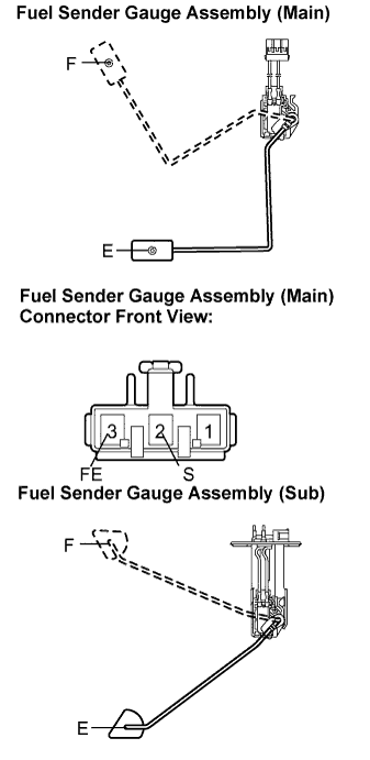

Inspect the fuel sender gauge assembly (main).
Remove the fuel sender gauge assembly (main).
Check that the float moves smoothly between F and E.
Measure the resistance between the terminals 2 (S) and 3 (FE) of connector according to the value(s) in the table below.
- Standard resistance:
- Main:
Float Level
Resistance (Ω)
F
6.5 to 8.5
Between E and F
6.5 to 242.6 (Gradually changes)
E
237.6 to 242.6
Inspect the fuel sender gauge assembly (sub).
Remove the fuel sender gauge assembly (sub).
Check that the float moves smoothly between F and E.
Measure the resistance between the terminals 1 (FS) and 2 (E) according to the value(s) in the table below.
- Standard resistance:
- Sub:
Float Level
Resistance (Ω)
F
6.5 to 8.5
Between E and F
6.5 to 171.9 (Gradually changes)
E
167.9 to 171.9
- HINT:
- If the value is not as specified, replace the fuel sender gauge assembly.