Operating Light Control Rheostat does not Change Light Brightness
Circuit diagnosis
DESCRIPTION
- The meter CPU receives signals for adjusting illumination on the meter and instrument panel from this circuit.
- The meter CPU detects the illumination level selected by the user according to the position of the rheostat knob.
- HINT:
- This model is equipped with an Optitron meter, therefore the meter illuminates even in the daytime.
- The meter illumination level can be adjusted by turning the rheostat.
- The meter illumination dims when the light control switch is turned to the TAIL or HEAD position at night.
- Turning the rheostat knob fully clockwise cancels the above dimmer control.
- Turning the rheostat knob fully counterclockwise turns the meter illumination off.
- This model is equipped with an Optitron meter, therefore the meter illuminates even in the daytime.
WIRING DIAGRAM
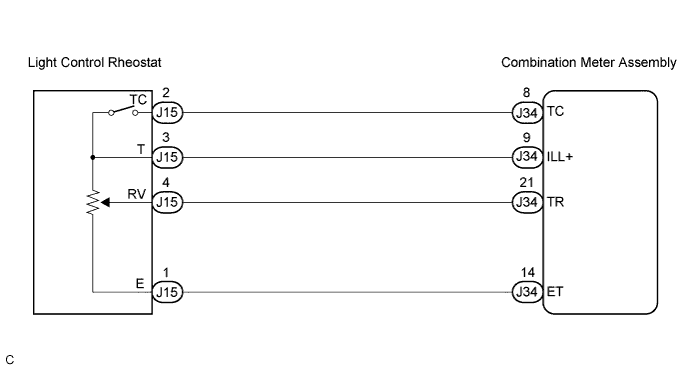

INSPECTION PROCEDURE
| 1. SYSTEM CHECK |

- Result:
Result
Proceed to
Meter illumination does not change when operate the light control rheostat knob
A
Dimmer cancel does not operate
B
|
|
||||

| A | |
 |
| 2. READ VALUE OF INTELLIGENT TESTER (RHEOSTAT VOL) |
Connect the intelligent tester to the DLC3.
Engine switch on (IG).
Turn the tester ON.
Enter the following menus: Diagnosis / Body / Combination Meter / Data List.
Check the values by referring to the table below.
Combination Meter: Item
Measurement Item/Range (Display)
Normal Condition
Diagnostic Note
Light Control Rheostat
Light control rheostat/Min.: 0, Max.: 255
Light control rheostat switch is Dark (0) → Bright (255)
-
- OK:
- The value displayed on the tester gradually changes as the actual rheostat operation.
|
|
||||
| OK | |
|
| 3. READ VALUE OF INTELLIGENT TESTER (TAIL CANCEL SW) |
Connect the intelligent tester to the DLC3.
Engine switch on (IG).
Turn the tester ON.
Enter the following menus: Diagnosis / Body / Combination Meter / Data List.
Check the values by referring to the table below.
Combination Meter: Item
Measurement Item/Range (Display)
Normal Condition
Diagnostic Note
Tail Cancel SW
Tail cancel switch is ON/OFF
ON: Light control rheostat turns fully clockwise
OFF: Light control rheostat position is except above.
-
- OK:
- Rheostat position displayed on the tester is same as the actual rheostat position.
|
|
||||
| OK | ||
 |
||
| ||
| 4. INSPECT LIGHT CONTROL RHEOSTAT |
Remove the light control rheostat with the connector still connected.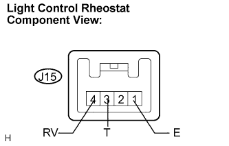
Measure the resistance according to the value(s) in the table below.
- Standard resistance:
Tester Connection
Condition
Specified Condition
E (J15-1) - RV (J15-4)
Turn the rheostat knob fully clockwise
8 to 12 kΩ
E (J15-1) - RV (J15-4)
Rheostat knob is between MIN. and MAX.
The value changes gradually
(Between approx. 0 to 8 kΩ)
E (J15-1) - RV (J15-4)
Turn the rheostat knob fully counterclockwise
Approx. 0 Ω
|
|
||||

| OK | |
|
| 5. CHECK HARNESS AND CONNECTOR (COMBINATION METER - LIGHT CONTROL RHEOSTAT) |
Disconnect the J34 and J15 connectors.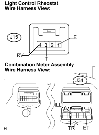
Measure the resistance according to the value(s) in the table below.
- Standard resistance:
Tester Connection
Condition
Specified Condition
J34-14 (ET) - J15-1 (E)
Always
Below 1 Ω
J34-9 (ILL+) - J15-3 (T)
Always
Below 1 Ω
J34-21 (TR) - J15-4 (RV)
Always
Below 1 Ω
J15-1 (E) - Body ground
Always
10 kΩ or higher
J15-3 (T) - Body ground
Always
10 kΩ or higher
J15-4 (RV) - Body ground
Always
10 kΩ or higher
|
|
||||
| OK | ||
|
||
| ||
| 6. READ VALUE OF INTELLIGENT TESTER (TAIL CANCEL SW) |
Connect the intelligent tester to the DLC3.
Engine switch on (IG).
Turn the tester ON.
Enter the following menus: Diagnosis / Body / Combination Meter / Data List.
Check the values by referring to the table below.
Combination Meter: Item
Measurement Item/Range (Display)
Normal Condition
Diagnostic Note
Tail Cancel SW
Tail cancel switch is ON/OFF
ON: Light control rheostat turns fully clockwise
OFF: Light control rheostat position is except above.
-
- OK:
- Rheostat position displayed on the tester is same as the actual rheostat position.
|
|
||||
| OK | ||
|
||
| ||
| 7. INSPECT LIGHT CONTROL RHEOSTAT |
Remove the light control rheostat with connector still connected.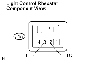
Measure the resistance according to the value(s) in the table below.
- Standard resistance:
Tester Connection
Condition
Specified Condition
T (J15-2) - TC (J15-3)
Turn the rheostat knob fully counterclockwise
Below 1 Ω
T (J15-2) - TC (J15-3)
Turn the rheostat knob fully clockwise
10 kΩ or higher
|
|
||||
| OK | |
|
| 8. CHECK HARNESS AND CONNECTOR (COMBINATION METER - LIGHT CONTROL RHEOSTAT) |
Disconnect the J34 and J15 connectors.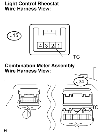
Measure the resistance according to the value(s) in the table below.
- Standard resistance:
Tester Connection
Condition
Specified Condition
J34-8 (TC) - J15-2 (TC)
Always
Below 1 Ω
J15-2 (TC) - Body ground
Always
10 kΩ or higher
|
|
||||
| OK | ||
|
||
| ||