AVC-LAN Circuit
Circuit diagnosis
DESCRIPTION
Each unit of the navigation system connected to the AVC-LAN (communication bus) transfers the signal of each switch by communication.When a short to +B or short to ground occurs in this AVC-LAN, the navigation system will not function normally as the communication is discontinued.
INSPECTION PROCEDURE
| 1. INSPECT RADIO RECEIVER |

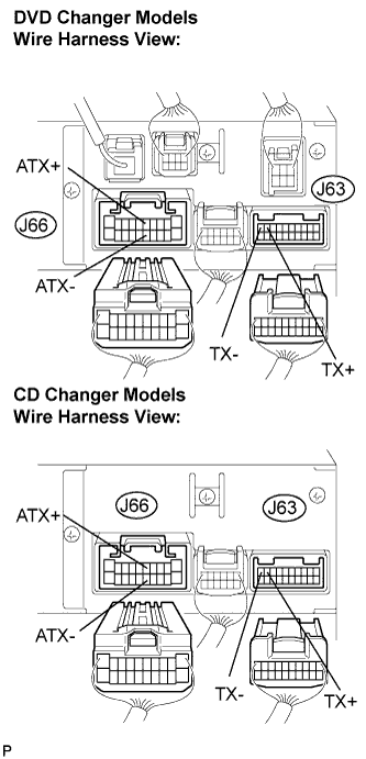  |
Disconnect the radio receiver connectors.
Measure the resistance according to the value(s) in the table below.
- Standard resistance:
Tester Connection
Condition
Specified Condition
ATX+ (J66-5) -
ATX- (J66-15)
Always
60 to 80 Ω
TX+ (J63-9) -
TX- (J63-10)
Always
60 to 80 Ω
|
|
||||

| OK | |
 |
| 2. CHECK HARNESS AND CONNECTOR |
- HINT:
- For details of the connectors, refer to "TERMINALS OF ECU" (Click here).
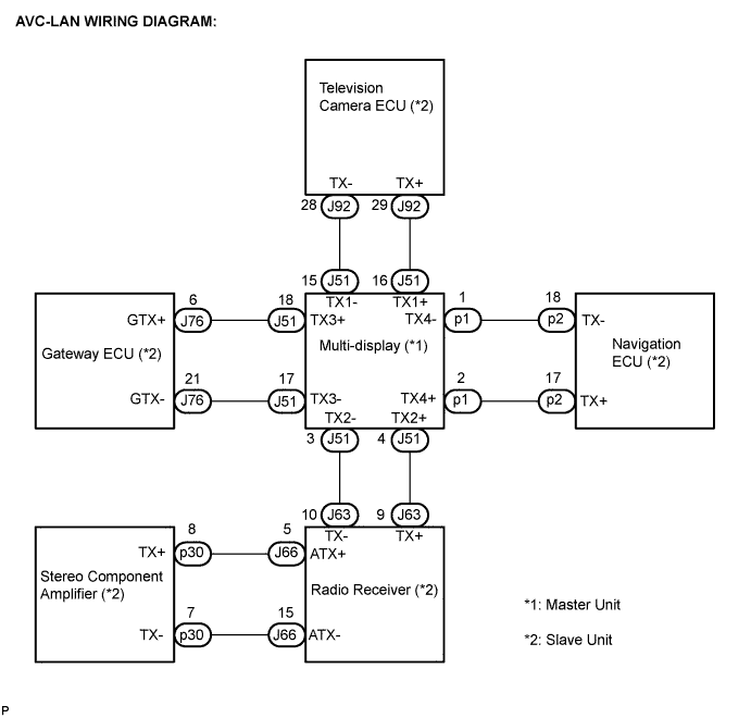
Referring to the AVC-LAN wiring diagram below, check all AVC-LAN circuits.
Disconnect all connectors in all AVC-LAN circuits.
Check for an open or short in all AVC-LAN circuits.
- OK:
- There is no open or short circuit.
|
|
||||
| OK | ||
 |
||
| ||