Parking Brake Switch Circuit
Circuit diagnosis
DESCRIPTION
This circuit is from the parking brake switch to the multi-display.WIRING DIAGRAM
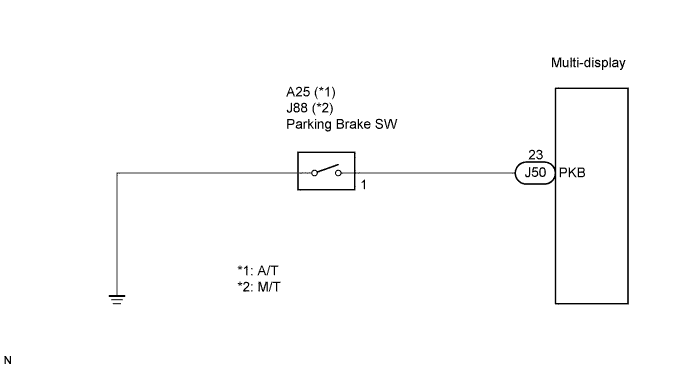

INSPECTION PROCEDURE
| 1. CHECK BRAKE WARNING LIGHT |

Check that the brake warning light comes on when the parking brake is applied and goes off when it is released.
- OK:
- The brake warning light operates as specified above.
|
|
||||

| NG | |
 |
| 2. INSPECT PARKING BRAKE SWITCH |
Remove the parking brake switch.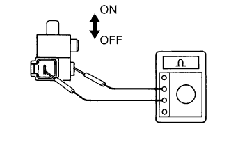
Measure the resistance according to the value(s) in the table below.
- Standard resistance:
Tester connection
Condition
Specified condition
Switch connector - Switch body
ON (When shaft is not pressed)
Below 1 Ω
Switch connector - Switch body
OFF (When shaft is pressed)
10 kΩ or higher
|
|
||||

| OK | |
|
| 3. CHECK HARNESS AND CONNECTOR (MULTI-DISPLAY - PARKING BRAKE SWITCH) |
Disconnect the multi-display connector J50 and parking brake switch connector A25 or J88.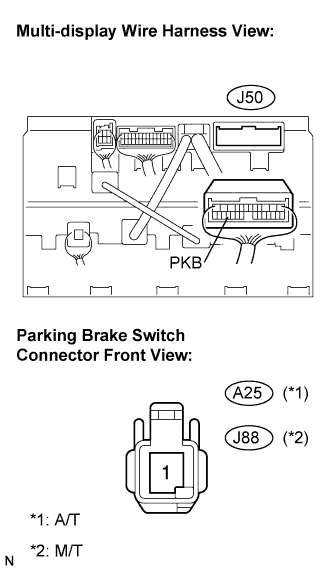
Measure the resistance according to the value(s) in the table below.
- Standard resistance:
Tester connection
Condition
Specified condition
PKB - A25-1 (A/T)
Always
Below 1 Ω
PKB - J88-1 (M/T)
Always
Below 1 Ω
PKB - Body ground
Always
10 kΩ or higher
|
|
||||
| OK | ||
 |
||
| ||