INSTALLATION
Removal / installation
| 1. INSTALL NETWORK GATEWAY ECU |

Install the network gateway ECU.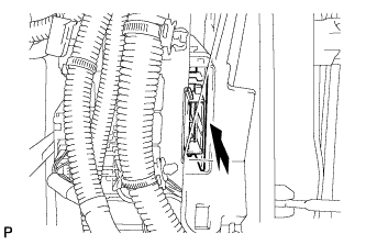

Engage the 2 claws to install the cover.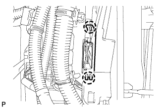
Connect the connector.
| 2. INSTALL GLOVE COMPARTMENT DOOR ASSEMBLY (for LHD) |
Connect the connectors.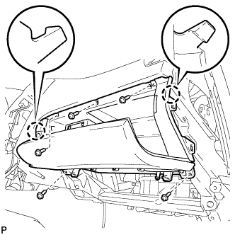
Engage the 2 claws.
Install the glove compartment door assembly with the 5 screws.
| 3. INSTALL FRONT PASSENGER SIDE KNEE AIRBAG ASSEMBLY (for LHD) |
| 4. INSTALL NO. 2 INSTRUMENT PANEL UNDER COVER SUB-ASSEMBLY (for LHD) |
Engage the 4 clips and install the No. 2 instrument panel under cover sub-assembly.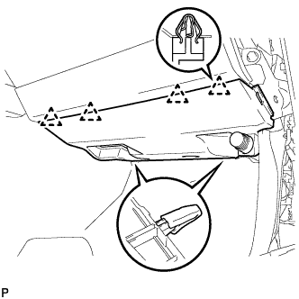
| 5. INSTALL LOWER INSTRUMENT PANEL FINISH PANEL SUB-ASSEMBLY (for RHD) |
Connect the connectors.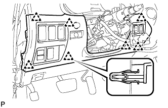
Engage the 7 clips and install the lower instrument panel finish panel sub-assembly.
| 6. INSTALL NO. 1 INSTRUMENT PANEL UNDER COVER SUB-ASSEMBLY (for RHD) |
Connect the connectors.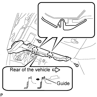
Insert the No. 1 instrument panel under cover sub-assembly into the guide as shown in the illustration.
Engage the 2 claws.
Install the No. 1 instrument panel under cover sub-assembly with the 2 screws <E>.
| 7. INSTALL SIDE INSTRUMENT PANEL |
Engage the 5 claws and 3 clips, and then install the side instrument panel RH.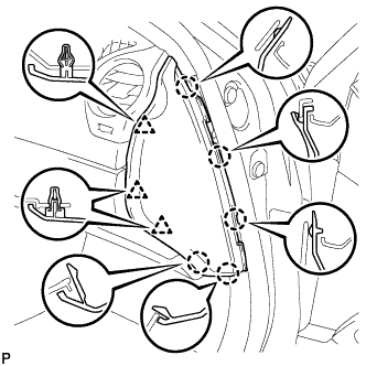
| 8. INSTALL FRONT DOOR OPENING TRIM COVER |
Engage the 6 claws and install the front door opening trim cover RH.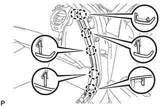
| 9. INSTALL FRONT DOOR SCUFF PLATE |
| 10. CONNECT CABLE TO NEGATIVE BATTERY TERMINAL |
| 11. PERFORM INITIALIZATION |
- NOTICE:
- Some systems need initialization when disconnecting the cable from the negative battery terminal (Click here).