Wireless Door Lock Buzzer Circuit
Circuit diagnosis
DESCRIPTION
The main body ECU RH activates the wireless door lock buzzer when detecting a lock/unlock signal from the door control transmitter.This function only equipped for Australia and New Zealand models.
WIRING DIAGRAM
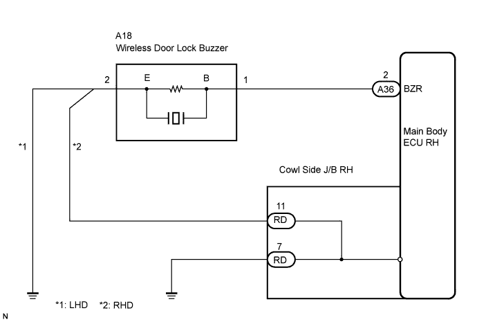

INSPECTION PROCEDURE
| 1. PERFORM ACTIVE TEST BY INTELLIGENT TESTER |

Connect the intelligent tester to the DLC3.
Turn the engine switch on (IG).
Turn the intelligent tester main switch on.
Select the Active test mode on the intelligent tester.
Main Body (Main Body ECU RH): Item (Display)
Tester Detail
Diagnostic Note
Buzz Resp Sound
Wireless door lock buzzer ON/OFF
Buzzer (operation sound) can be heard
Check that the buzzer sounds/stops when turning the wireless door lock buzzer on/off by using intelligent tester.
Result Condition
Proceed to
Buzzer sounds/stops
A
Buzzer does not sound or sounds constantly
B
|
|
||||

| A | ||
 |
||
| ||
| 2. CHECK HARNESS AND CONNECTOR (MAIN BODY ECU RH - WIRELESS DOOR LOCK BUZZER) |
Disconnect the A36 main body ECU RH connector.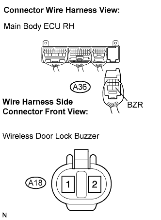
Measure the resistance according to the value(s) in the table below.
- Standard resistance:
Symbol (Tester Connection)
Condition
Specified Condition
BZR (A36-2) - A18-1
Always
Below 1 Ω
BZR (A36-2) - Body ground
Always
10 kΩ or higher
|
|
||||

| OK | |
 |
| 3. CHECK HARNESS AND CONNECTOR (WIRELESS DOOR LOCK BUZZER - COWL SIDE J/B RH - BODY GROUND) |
Disconnect RD J/B connector.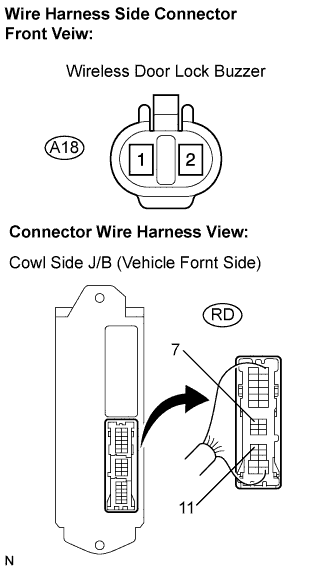
Measure the resistance according to the value(s) in the table below.
- Standard resistance:
Tester Connection
Condition
Specified Condition
A18-2 - RD-11
Always
Below 1 Ω
A18-2 - Body ground
Always
10 kΩ or higher
RD-7 - Body ground
Always
Below 1 Ω
|
|
||||
| OK | |
|
| 4. INSPECT WIRELESS DOOR LOCK BUZZER |
Disconnect the A18 wireless door lock buzzer connector.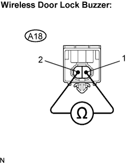
Measure the resistance according to the value(s) in the table below.
- HINT:
- The buzzer circuit is built into the ECU, not into the buzzer itself. When battery voltage is applied directly to the buzzer, the buzzer will not sound.
- Standard resistance:
Tester Connection
Condition
Specified Condition
A18-1 - A18-2
Always
Approx. 1 kΩ
|
|
||||
| OK | ||
|
||
| ||