Power Source Circuit
Circuit diagnosis
DESCRIPTION
Certification ECU provides power for the door control receiver operation.WIRING DIAGRAM
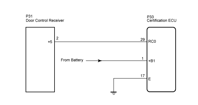

INSPECTION PROCEDURE
| 1. CHECK HARNESS AND CONNECTOR (CERTIFICATION ECU - DOOR CONTROL RECEIVER) |

Disconnect the P33 certification ECU connector and P31 door control receiver connector.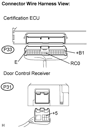
Measure the voltage resistance according to the value(s) in the table below.
- Standard:
Symbol
(Tester Connection)
Condition
Specified Condition
RC0 (P33-29) - +5 (P31-2)
Always
Below 1 Ω
+B1 (P33-1) - Body ground
Always
10 to 14 V
RC0 (P33-29) - Body ground
Always
10 kΩ or higher
E (P33-17) - Body ground
Always
Below 1 Ω
|
|
||||

| OK | |
 |
| 2. INSPECT CERTIFICATION ECU |
Reconnect the P33 connector.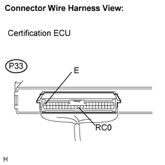
Measure the voltage according to value(s) in the table below.
- Standard voltage:
Symbol
(Tester Connection)
Condition
Specified Condition
RC0 (P33-29) - E (P33-17)
Engine switch OFF, all doors closed and transmitter switch not pressed
Below 1 V
Engine switch OFF, all doors closed and transmitter switch pressed
4.6 to 5.4 V
+B1 (P33-1) - E
Always
10 to 14 V
|
|
||||
| OK | ||
 |
||
| ||