PTC Heater Circuit
Circuit diagnosis
DESCRIPTION
The GLW RLY turns on when it receives a signal from the A/C amplifier. As a result, power is supplied to the heater glow plug.WIRING DIAGRAM
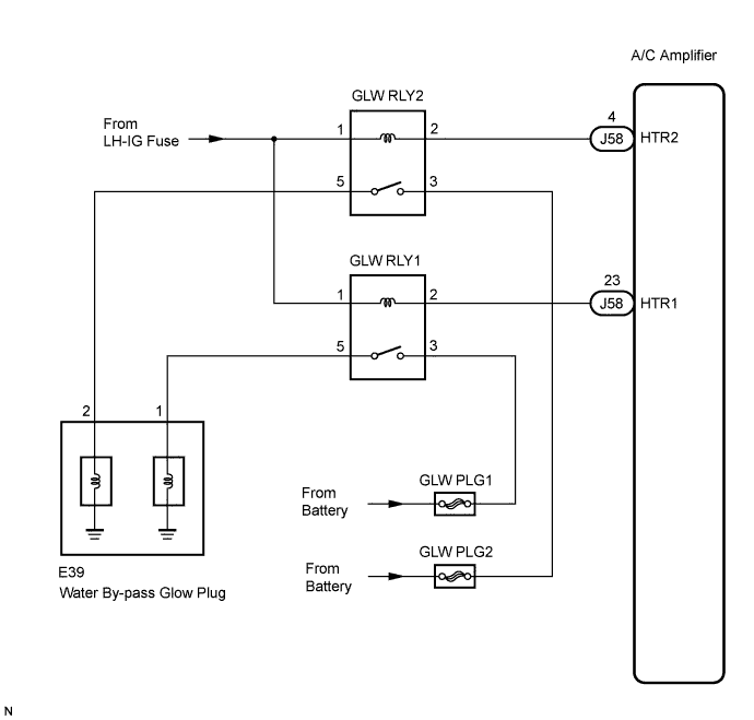

INSPECTION PROCEDURE
| 1. INSPECT FUSE (LH-IG, GLW PLG1, GLW PLG2) |

Remove the LH-IG fuse from the cowl side J/B LH.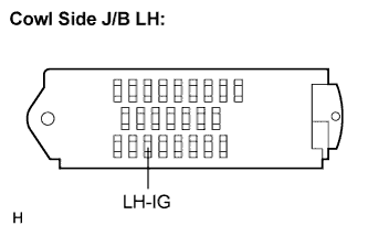
Remove the GLW PLG1 and GLW PLG2 fuses from the engine room R/B and J/B No. 1.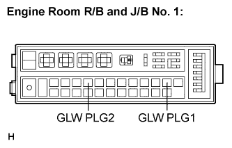
Measure the resistance according to the value(s) in the table below.
- Standard resistance:
Tester Item
Condition
Specified Condition
LH-IG fuse
Always
Below 1 Ω
GLW PLG1 fuse
Always
Below 1 Ω
GLW PLG2 fuse
Always
Below 1 Ω
|
|
||||

| OK | |
 |
| 2. INSPECT RELAY (GLW RLY1, GLW RLY2) |
Remove the GLW RLY1 and GLW RLY2 relays from the engine room R/B and J/B No. 1.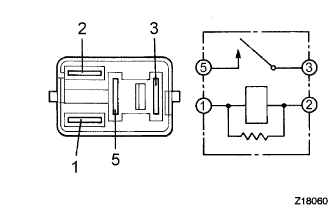
Measure the resistance according to the value(s) in the table below.
- Standard resistance:
Tester Connection
Condition
Specified Condition
3 - 5
Always
10 kΩ or higher
3 - 5
When battery voltage is applied to terminals 1 and 2
Below 1 Ω
|
|
||||
| OK | |
|
| 3. CHECK HARNESS AND CONNECTOR (A/C AMPLIFIER - BATTERY) |
Disconnect the connector from the A/C amplifier.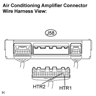
Turn the engine switch on (IG).
Measure the voltage according to the value(s) in the table below.
- Standard voltage:
Tester Connection (Symbols)
Condition
Specified Condition
J58-4 (HTR2) - Body ground
Engine switch on (IG)
10 to 14 V
J58-23 (HTR1) - Body ground
Engine switch on (IG)
10 to 14 V
|
|
||||
| OK | |
|
| 4. INSPECT AIR CONDITIONING AMPLIFIER |
Reconnect the connector to the A/C amplifier.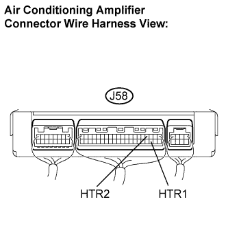
Measure the voltage according to the value(s) in the table below.
- Standard voltage:
Tester Connection
Condition
Specified Condition
J58-4 (HTR2) - Body ground
Engine switch on (IG)
10 to 14 V
J58-4 (HTR2) - Body ground
Engine switch on (IG)
While the PTC operating conditions are met (engine is running at 850 rpm or more, ambient temperature is 0°C (32°F) or less, engine coolant temperature is 69°C (156°F) or less, and A/C switch setting is MAX HOT), turn the blower switch to the LO setting.
Below 1 V
J58-23 (HTR1) - Body ground
Engine switch on (IG)
10 to 14 V
D47-2 - Body ground
Engine switch on (IG)
While the PTC operating conditions are met (engine is running at 850 rpm or more, ambient temperature is 0°C (32°F) or less, engine coolant temperature is 69°C (156°F) or less, and A/C switch setting is MAX HOT), turn the blower switch to the LO setting.
Below 1 V
|
|
||||
| OK | |
|
| 5. INSPECT HEATER BLOWER WIRE |
Remove the grommets and nuts of the water by-pass glow plugs.
Turn the engine switch on (IG).
Perform Active Test by referring to the table below.
Active Test / Air Conditioner: Item
Test Details / Display (Range)
Diagnostic Note
Electric Heater 1
(Heater 1)
Electric Heater 1 / OFF, ON
-
Electric Heater 2
(Heater 2)
Electric Heater 2 / OFF, ON
-
Measure the voltage according to the value(s) in the table below.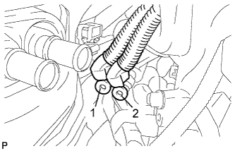
- Standard voltage:
Tester connection
Condition
Specified condition
1 - Body ground
Perform Active Test / HEATER 1 (Electric Heater 1): ON
10 to 14 V
2 - Body ground
Perform Active Test / HEATER 2 (Electric Heater 2): ON
10 to 14 V
|
|
||||
| OK | |
|
| 6. INSPECT WATER BY-PASS GLOW PLUG |
Remove the water by-pass glow plug.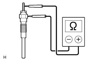
Measure the resistance according to the value(s) in the table below.
- Standard resistance:
- Below 1 Ω
|
|
||||
| OK | ||
 |
||
| ||