INSTALLATION
Removal / installation
| 1. INSTALL ANTENNA CORD SUB-ASSEMBLY (w/o DVD Player) |

Install the antenna cord sub-assembly with the 3 bolts.
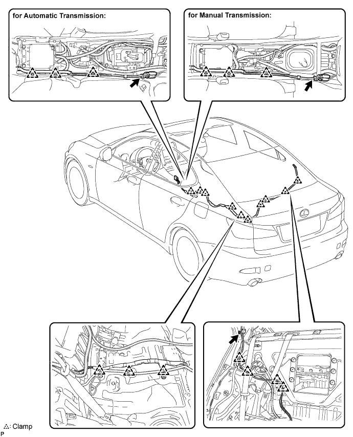

Engage the 19 clamps.
Connect the connectors.
| 2. INSTALL ANTENNA CORD SUB-ASSEMBLY (w/ DVD Player) |
Install the antenna cord sub-assembly with the 3 bolts.
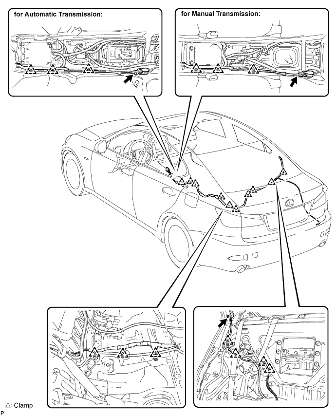
Engage the 19 clamps.
Connect the connectors.
Engage the 3 clamps.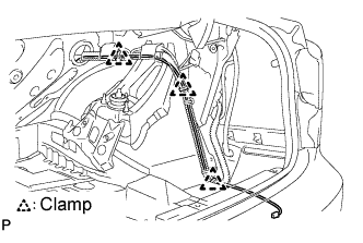
Connect the connectors.
| 3. INSTALL SIDE LUGGAGE COMPARTMENT TRIM COVER (w/ DVD Player) |
| 4. INSTALL LUGGAGE COMPARTMENT TRIM HOOK (w/ DVD Player) |
| 5. INSTALL FRONT LUGGAGE COMPARTMENT TRIM COVER (w/ DVD Player) |
| 6. INSTALL ROPE HOOK (w/ DVD Player) |
| 7. INSTALL ROOM LIGHT ASSEMBLY (w/ DVD Player) |
| 8. INSTALL REAR LUGGAGE COMPARTMENT TRIM COVER (w/ DVD Player) |
| 9. INSTALL ROPE HOOK ASSEMBLY (w/ DVD Player) |
| 10. INSTALL SPARE WHEEL COVER (w/ DVD Player) |
| 11. INSTALL DECK SIDE TRIM BOX LH (w/ DVD Player) |
| 12. INSTALL DECK SIDE TRIM BOX RH (w/ DVD Player) |
| 13. INSTALL LUGGAGE COMPARTMENT TRIM COVER (w/ DVD Player) |
| 14. INSTALL ROOF SIDE INNER GARNISH |
| 15. INSTALL REAR SIDE SEAT GARNISH |
| 16. INSTALL REAR DOOR SCUFF PLATE |
| 17. INSTALL REAR SEATBACK ASSEMBLY |
Place the seatback in the cabin.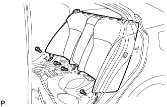
- NOTICE:
- Be careful not to damage the vehicle body.
Install the seatback with the 4 bolts.
- Torque:
- 18 N*m{ 184 kgf*cm , 13 ft.*lbf }
Pass the 3 seat belts through and close the cap of the 2 rear seat shoulder belt guides.
Install the floor anchor part with the bolt.
| 18. INSTALL REAR CENTER SEAT HEADREST ASSEMBLY |
| 19. INSTALL REAR SEAT HEADREST ASSEMBLY |
| 20. INSTALL REAR SEAT CUSHION ASSEMBLY |
Attach the 2 rear hooks of the seat cushion to the seatback.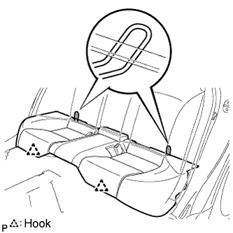
Attach the 2 front hooks of the seat cushion to the vehicle body.
Confirm that the seat cushion is firmly installed.
- NOTICE:
- When installing the seat cushion, make sure the seat belt buckle is not under the seat cushion.
| 21. INSTALL NO. 2 ANTENNA CORD SUB-ASSEMBLY |
Engage the clamp and install the No. 2 antenna cord sub-assembly.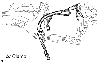
| 22. INSTALL INSTRUMENT PANEL SAFETY PAD ASSEMBLY |
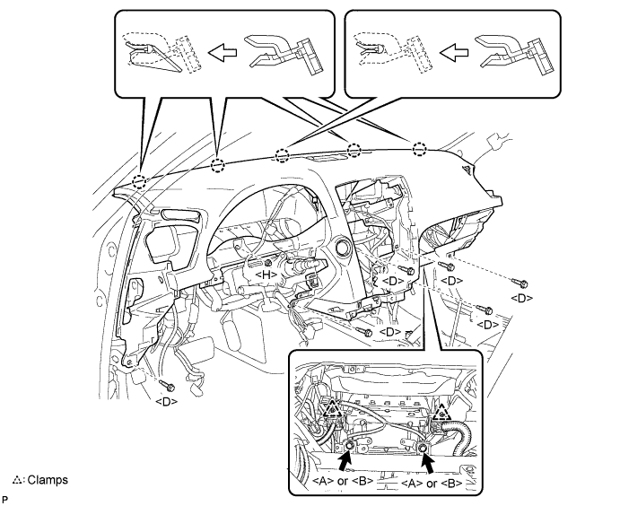
Engage the 5 claws.
- NOTICE:
- Do not allow the wire harness to get caught in the claws.
Engage the 2 clamps.
Install the 2 passenger airbag bolts <A> or <B>.
- Torque:
- 20 N*m{ 204 kgf*cm , 15 ft.*lbf }
Install the 6 bolts <D> and nut <H>.
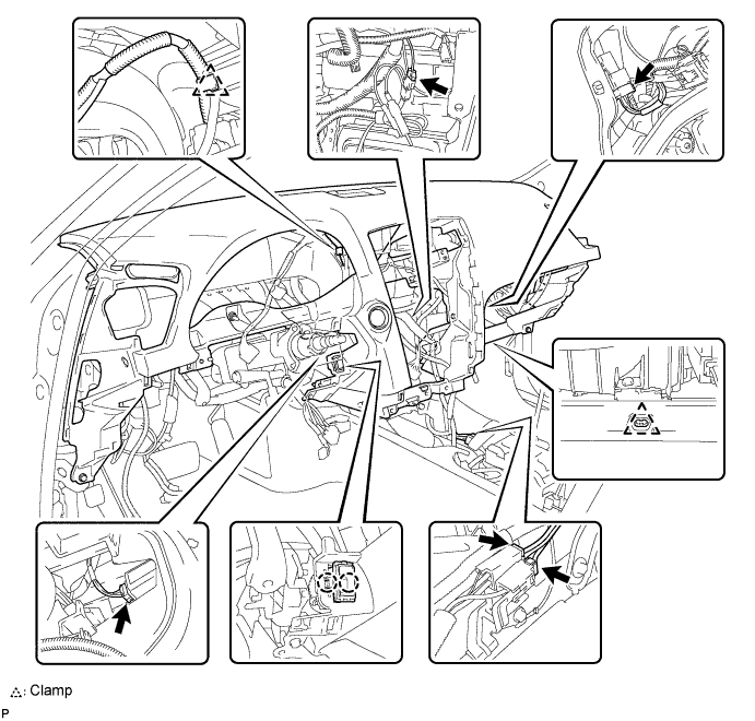
Engage the 2 claws and install the cooler thermistor.
Engage the clamps.
Connect the connectors and install the instrument panel safety pad assembly.
| 23. CONNECT PASSENGER AIRBAG CONNECTOR |
| 24. INSTALL NO. 2 CONSOLE BOX DUCT (for Manual Transmission) |
Install the No. 2 console box duct with the clip.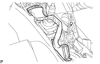
| 25. INSTALL NO. 1 CONSOLE BOX DUCT (for Automatic Transmission) |
Install the No. 1 console box duct with the clip.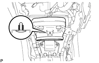
| 26. INSTALL NO. 2 CONSOLE BOX DUCT (for Automatic Transmission) |
Install the No. 2 console box duct with the 2 clips.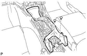
| 27. INSTALL FRONT STEREO COMPONENT SPEAKER ASSEMBLY |
Connect the connector.
Install the front stereo component speaker assembly with the 2 bolts.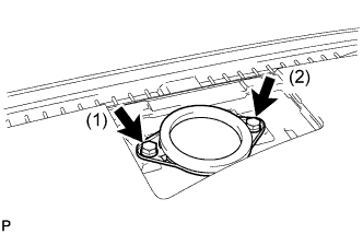
- HINT:
- Install the bolts in the order shown in the illustration.
| 28. INSTALL NO. 3 INSTRUMENT PANEL SPEAKER PANEL SUB-ASSEMBLY |
Engage the 7 claws and install the No. 3 instrument panel speaker panel sub-assembly.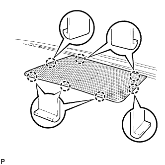
| 29. INSTALL NO. 2 INSTRUMENT PANEL REGISTER ASSEMBLY |
Connect the connector.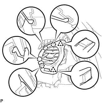
Engage the 4 claws and 2 clips, and install the No. 2 instrument panel register assembly.
| 30. INSTALL NO. 1 INSTRUMENT PANEL REGISTER ASSEMBLY |
Connect the connector.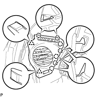
Engage the 7 claws and 2 clips, and install the No. 1 instrument panel register assembly.
| 31. INSTALL FRONT PILLAR GARNISH LH |
Install a new clip <A> on the front pillar garnish LH.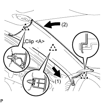
Engage the claw and 2 clips, and install the front pillar garnish LH.
| 32. INSTALL FRONT PILLAR GARNISH RH |
| 33. INSTALL GLOVE COMPARTMENT DOOR ASSEMBLY |
Connect the connectors.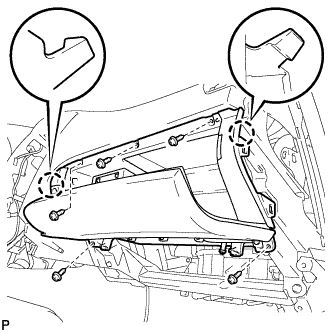
Engage the 2 claws.
Install the glove compartment door assembly with the 5 screws.
| 34. INSTALL FRONT PASSENGER SIDE KNEE AIRBAG ASSEMBLY |
Connect the connector.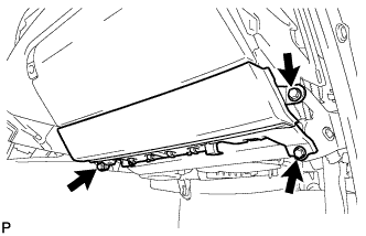
- NOTICE:
- When handling the airbag connector, take care not to damage the airbag wire harness.
Install the front passenger side knee airbag assembly with the 3 bolts.
- Torque:
- 10 N*m{ 102 kgf*cm , 7 ft.*lbf }
| 35. INSTALL NO. 2 INSTRUMENT PANEL UNDER COVER SUB-ASSEMBLY |
Engage the 4 clips and install the No. 2 instrument panel under cover sub-assembly.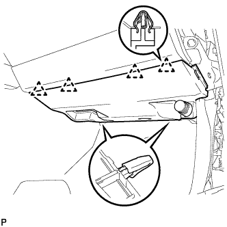
| 36. INSTALL SIDE INSTRUMENT PANEL RH |
Engage the 5 claws and 3 clips, and then install the side instrument panel RH.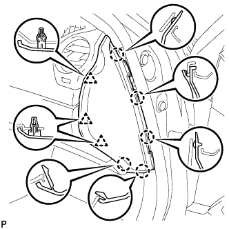
| 37. INSTALL FRONT DOOR OPENING TRIM COVER RH |
Engage the 6 claws and install the front door opening trim cover RH.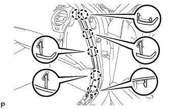
| 38. INSTALL FRONT DOOR SCUFF PLATE RH (w/o Illumination) |
| 39. INSTALL FRONT DOOR SCUFF PLATE RH (w/ Illumination) |
| 40. INSTALL COMBINATION METER ASSEMBLY |
Connect the connectors.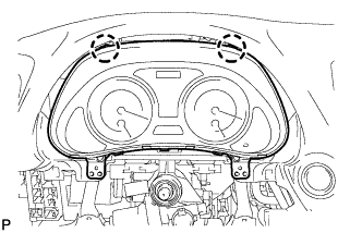
Engage the 2 claws and install the combination meter assembly.
| 41. INSTALL INSTRUMENT CLUSTER FINISH PANEL SUB-ASSEMBLY |
Install the instrument cluster finish panel sub-assembly with the 2 screws and 2 clips.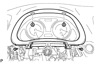
| 42. INSTALL DRIVER SIDE KNEE AIRBAG ASSEMBLY |
Connect the connector.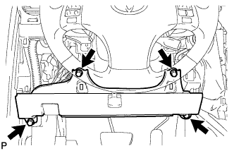
- NOTICE:
- When handling the airbag connector, take care not to damage the airbag wire harness.
Install the driver side knee airbag assembly with the 4 bolts.
- Torque:
- 10 N*m{ 102 kgf*cm , 7 ft.*lbf }
| 43. INSTALL LOWER INSTRUMENT PANEL FINISH PANEL SUB-ASSEMBLY |
Connect the connectors.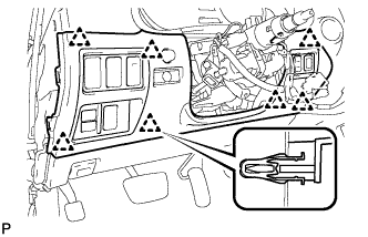
Engage the 7 clips and install the lower instrument panel finish panel sub-assembly.
| 44. INSTALL NO. 1 INSTRUMENT PANEL UNDER COVER SUB-ASSEMBLY |
Connect the connectors.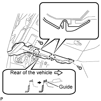
Insert the No. 1 instrument panel under cover sub-assembly into the guide as shown in the illustration.
Engage the 2 claws.
Install the No. 1 instrument panel under cover sub-assembly with the 2 screws <E>.
| 45. INSTALL SIDE INSTRUMENT PANEL LH |
Engage the 5 claws and 3 clips, and then install the side instrument panel LH.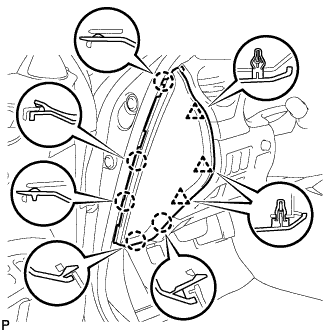
| 46. INSTALL FRONT DOOR OPENING TRIM COVER LH |
Engage the 6 claws and install the front door opening trim cover LH.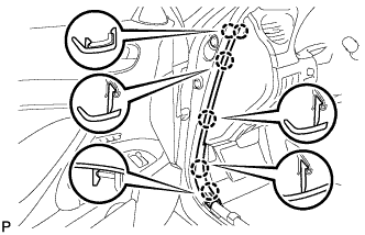
| 47. INSTALL FRONT DOOR SCUFF PLATE LH (w/o Illumination) |
Engage the 4 clips.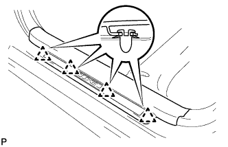
Engage the 7 claws, and install the front door scuff plate LH.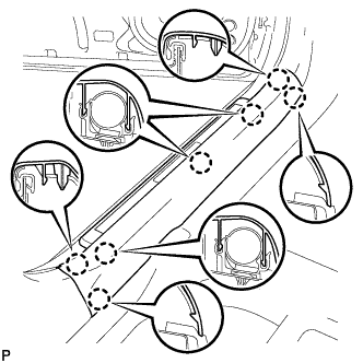
| 48. INSTALL FRONT DOOR SCUFF PLATE LH (w/ Illumination) |
Connect the connector.
Engage the 4 clips.
Engage the 7 claws, and install the front door scuff plate LH.
| 49. INSTALL TURN SIGNAL SWITCH ASSEMBLY WITH SPIRAL CABLE SUB-ASSEMBLY |
Install the turn signal switch assembly with spiral cable sub-assembly to the steering column assembly with the clamp.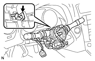
| 50. INSTALL STEERING COLUMN COVER (for Manual Tilt and Telescopic) |
Engage the claw to install the upper steering column cover.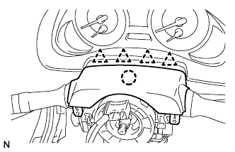
Engage the 4 clips to install the steering column cover upper onto the instrument panel cluster finish panel.
Engage the 2 claws to install the lower steering column cover.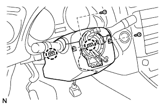
Install the 2 screws.
- Torque:
- 2.0 N*m{ 20 kgf*cm , 18 in.*lbf }
| 51. INSTALL STEERING COLUMN COVER (for Power Tilt and Power Telescopic) |
Engage the claw to install the steering column cover upper.
Engage the 4 clips to install the steering column cover upper onto the instrument panel cluster finish panel.
Engage the 2 claws to install the steering column cover lower.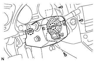
- NOTICE:
- Do not damage the tilt and telescopic switch.
Install the 3 screws.
- Torque:
- 2.0 N*m{ 20 kgf*cm , 18 in.*lbf }
| 52. ADJUST SPIRAL CABLE SUB-ASSEMBLY |
Check that the engine switch is off.
Check that the battery negative (-) terminal is disconnected.
- CAUTION:
- After removing the terminal, wait for at least 90 seconds before starting the operation.
Rotate the spiral cable with steering sensor counterclockwise slowly by hand until it feels firm.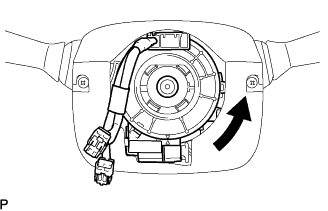
- NOTICE:
- Do not turn the spiral cable with steering sensor by the airbag wire harness.
Rotate the spiral cable with steering sensor clockwise approximately 2.5 turns to align the marks.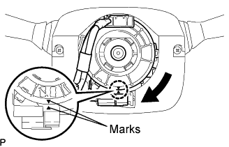
- NOTICE:
- Do not turn the spiral cable with spiral sensor by the airbag wire harness.
- HINT:
- The spiral cable with steering sensor will rotate approximately 2.5 turns to both the left and right from the center.
| 53. INSTALL STEERING WHEEL ASSEMBLY |
Align the matchmarks on the steering wheel assembly and steering main shaft assembly.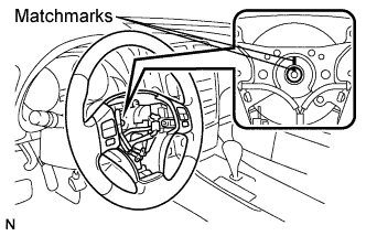
Install the steering wheel assembly set nut.
- Torque:
- 50 N*m{ 510 kgf*cm , 37 ft.*lbf }
| 54. INSTALL STEERING PAD |
Support the steering pad with one hand as shown in the illustration.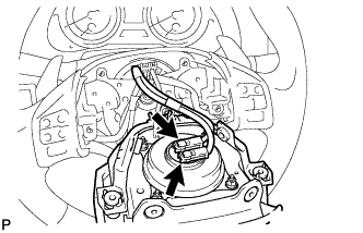
Connect the 2 connectors to the steering pad.
- NOTICE:
- When handling the airbag connector, take care not to damage the airbag wire harness.
Connect the horn connector.
Confirm that the circumference groove of the "torx" screw fits in the screw case, and place the steering pad onto the steering wheel assembly.
Using a "torx" socket wrench (T30), tighten the 2 "torx" screws.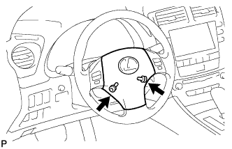
- Torque:
- 8.8 N*m{ 90 kgf*cm , 78 in.*lbf }
| 55. INSTALL LOWER NO. 3 STEERING WHEEL COVER |
Install the steering wheel No.3 cover lower.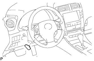
| 56. INSTALL LOWER NO. 2 STEERING WHEEL COVER |
Install the steering wheel No.2 cover lower.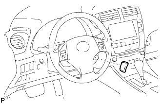
| 57. INSTALL INTEGRATION CONTROL PANEL WITH RADIO RECEIVER ASSEMBLY (w/o Navigation System) |
Connect each connector.
Install the integration control panel w/ radio receiver assembly with the 4 bolts.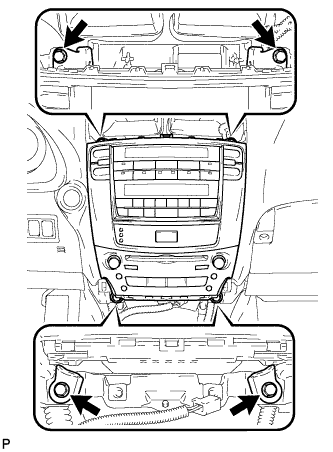
| 58. INSTALL MULTI-DISPLAY WITH RADIO RECEIVER ASSEMBLY (w/ Navigation System) |
Connect each connector.
Install the the multi-display w/ radio receiver assembly with the 4 bolts.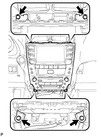
| 59. INSTALL CENTER LOWER INSTRUMENT CLUSTER FINISH PANEL |
Engage the 4 claws and install the center lower instrument cluster finish panel.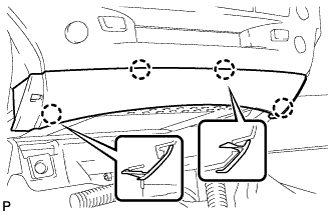
| 60. INSTALL NO. 3 INSTRUMENT PANEL REGISTER ASSEMBLY |
Connect the connectors.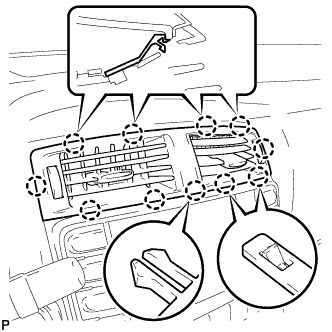
Engage the 11 claws and install the No. 3 instrument panel register assembly.
| 61. INSTALL CONSOLE BOX |
Engage the 2 claws and 2 clips.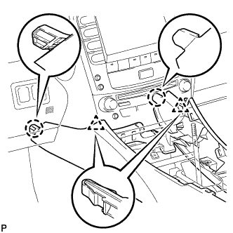
Install the 2 bolts <C>.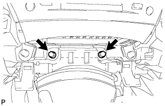
Install the 2 bolts <C>.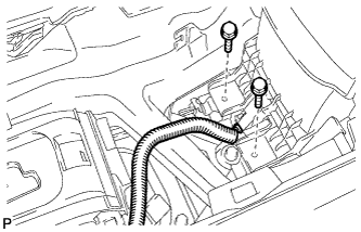
Connect the connector.
Connect the connectors.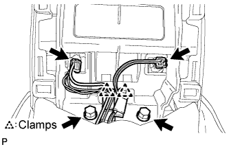
Engage the 2 clamps.
Install the 2 bolts <C>.
| 62. INSTALL CONSOLE BOX REGISTER ASSEMBLY |
Engage the 2 claws and 4 clips, and then install the console box register assembly.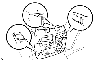
Install the rear ash receptacle assembly.
| 63. INSTALL FRONT ASH RECEPTACLE SUB-ASSEMBLY |
Connect the connectors.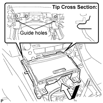
Insert the protruding parts of the front ash receptacle sub-assembly into the 2 guide holes as shown in the illustration.
Install the front ash receptacle sub-assembly with the 2 screws <F>.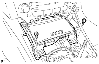
| 64. INSTALL FRONT CONSOLE PANEL SUB-ASSEMBLY (for Manual Transmission) |
Engage the 6 clips.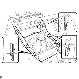
Close the snap.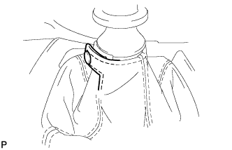
| 65. INSTALL REAR CONSOLE PANEL SUB-ASSEMBLY (for Manual Transmission) |
Engage the 7 claws and 2 clips.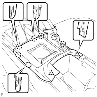
Close the snap.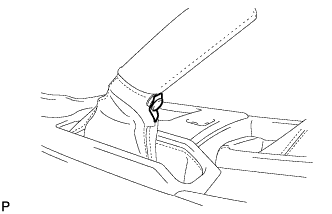
| 66. INSTALL CONSOLE PANEL SUB-ASSEMBLY (for Automatic Transmission) |
Connect the connectors.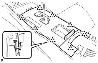
Engage the 8 clips and install the console panel sub-assembly.
| 67. INSTALL UPPER NO. 2 CONSOLE PANEL GARNISH (for Automatic Transmission) |
Engage the claw and 2 clips, and then install the upper No. 2 console panel garnish.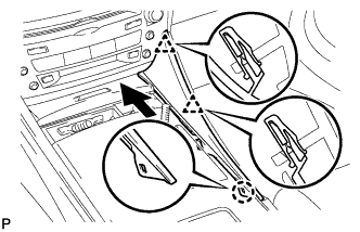
| 68. INSTALL UPPER NO. 1 CONSOLE PANEL GARNISH (for Automatic Transmission) |
Engage the claw and 2 clips, and then install the upper No. 1 console panel garnish.
| 69. INSTALL SHIFT LEVER KNOB SUB-ASSEMBLY (for Manual Transmission) |
| 70. INSTALL SHIFT LEVER KNOB SUB-ASSEMBLY (for Automatic Transmission) |
| 71. CONNECT CABLE TO NEGATIVE BATTERY TERMINAL |
| 72. PERFORM INITIALIZATION |
- NOTICE:
- Some systems need initialization after reconnecting the cable to the negative battery terminal (Click here).
| 73. INSPECT STEERING PAD |
With the steering pad installed on the vehicle, perform a visual check. If there are any defects as mentioned below, replace the steering pad with a new one: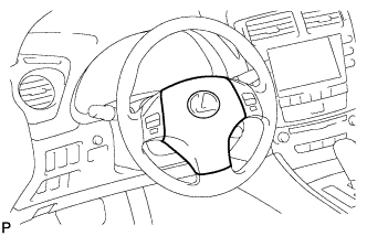
- Cuts, minute cracks or marked discoloration on the steering pad top surface or in the grooved portion.
- Cuts, minute cracks or marked discoloration on the steering pad top surface or in the grooved portion.
Make sure that the horn sounds.
- HINT:
- If the horn does not sound, inspect the horn system (Click here).
| 74. INSPECT SRS WARNING LIGHT |