REMOVAL
Removal / installation
| 1. PRECAUTION |

| 2. ALIGN FRONT WHEELS FACING STRAIGHT AHEAD |
| 3. DISCONNECT CABLE FROM NEGATIVE BATTERY TERMINAL |
- CAUTION:
- Wait for 90 seconds after disconnecting the cable to prevent airbag deployment (Click here).
| 4. REMOVE SHIFT LEVER KNOB SUB-ASSEMBLY (for Automatic Transmission) |
Turn the shift lever knob counterclockwise and remove the shift lever knob sub-assembly.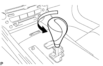

| 5. REMOVE SHIFT LEVER KNOB SUB-ASSEMBLY (for Manual Transmission) |
Turn the shift lever knob counterclockwise and remove the shift lever knob sub-assembly.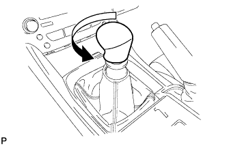
| 6. REMOVE UPPER NO. 1 CONSOLE PANEL GARNISH (for Automatic Transmission) |
Using a moulding remover, disengage the claw.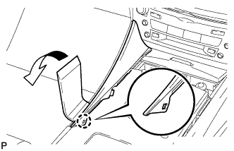
Pull the upper No. 1 console panel garnish in the direction indicated by the arrow to disengage the 2 clips and remove it.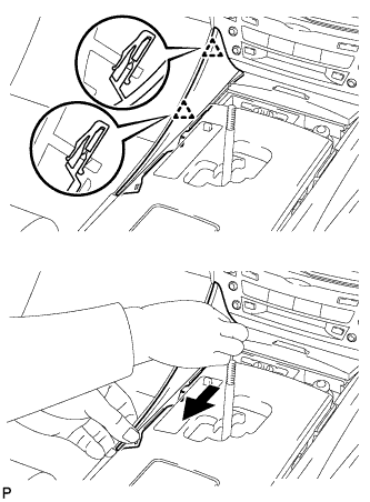
| 7. REMOVE UPPER NO. 2 CONSOLE PANEL GARNISH (for Automatic Transmission) |
Using a moulding remover, disengage the claw.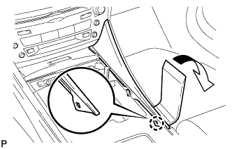
Pull the upper No. 2 console panel garnish in the direction indicated by the arrow to disengage the 2 clips and remove it.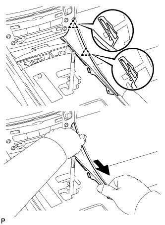
| 8. REMOVE CONSOLE PANEL SUB-ASSEMBLY (for Automatic Transmission) |
Disengage the 8 clips.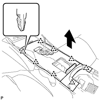
Disconnect the connectors and remove the console panel sub-assembly.
| 9. REMOVE REAR CONSOLE PANEL SUB-ASSEMBLY (for Manual Transmission) |
Open the snap.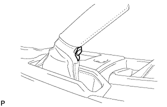
Disengage the 7 claws and 2 clips, and then remove the rear console panel sub-assembly.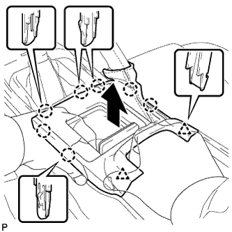
| 10. REMOVE FRONT CONSOLE PANEL SUB-ASSEMBLY (for Manual Transmission) |
Open the snap.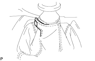
Pull the front console panel sub-assembly in the direction indicated by the arrow to disengage the 6 clips and remove it.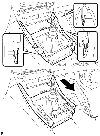
| 11. REMOVE FRONT ASH RECEPTACLE SUB-ASSEMBLY |
Remove the 2 screws <F>.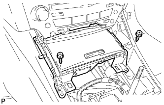
Pull the front ash receptacle sub-assembly in the direction indicated by the arrow to disconnect the connectors and remove it.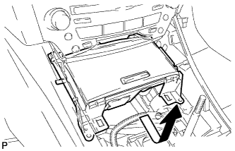
| 12. REMOVE CONSOLE BOX REGISTER ASSEMBLY |
Remove the rear ash receptacle assembly.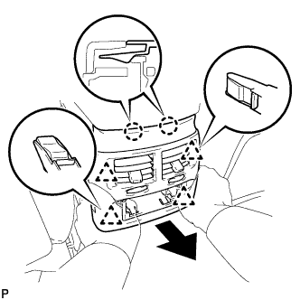
Disengage the 2 claws and 4 clips, and then remove the console box register assembly.
| 13. REMOVE CONSOLE BOX |
Remove the 2 bolts <C>.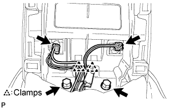
Disconnect the 2 connectors.
Disengage the 2 clamps.
Remove the 2 bolts <C>.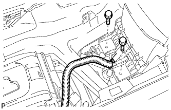
Disconnect the connector.
Remove the 2 bolts <C>.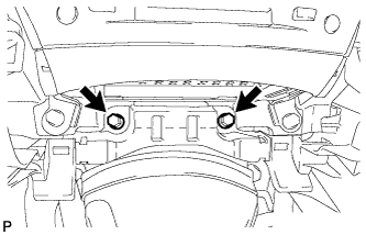
Disengage the 2 claws and 2 clips, and then remove the console box.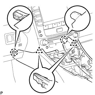
| 14. REMOVE NO. 3 INSTRUMENT PANEL REGISTER ASSEMBLY |
Using a screwdriver, disengage the 4 claws.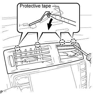
- HINT:
- Tape the screwdriver tip before use.
Apply protective tape to the areas shown in the illustration.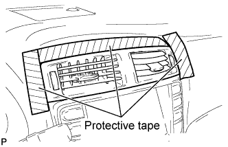
Using a moulding remover, disengage the 4 claws starting from the right of the No. 3 instrument panel register assembly. Disengage the remaining 3 claws by pulling the No. 3 instrument panel register assembly by hand.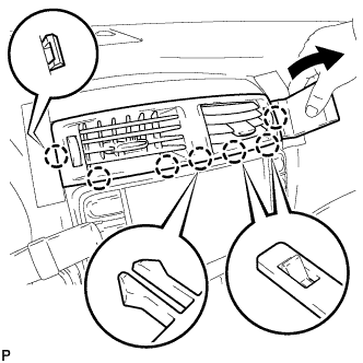
- NOTICE:
- Do not pry the lower part of the No. 3 instrument panel register assembly. Doing so may damage the assembly.
Disconnect the connectors.
| 15. REMOVE CENTER LOWER INSTRUMENT CLUSTER FINISH PANEL |
Disengage the 4 claws and remove the center lower instrument cluster finish panel.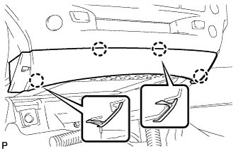
| 16. REMOVE MULTI-DISPLAY WITH RADIO RECEIVER ASSEMBLY (w/ Navigation System) |
Remove the 4 bolts.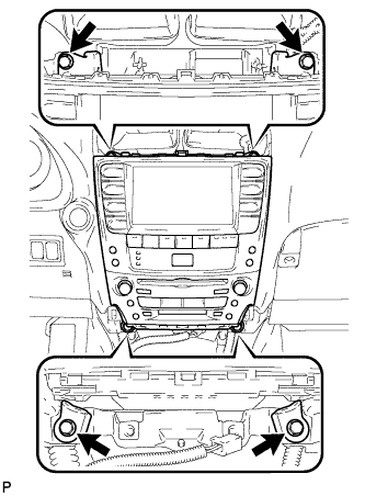
Pull the multi-display w/ radio receiver assembly toward the rear of the vehicle.
Disconnect each connector and remove the multi-display.
| 17. REMOVE INTEGRATION CONTROL PANEL WITH RADIO RECEIVER ASSEMBLY (w/o Navigation System) |
Remove the 4 bolts.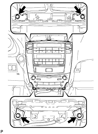
Pull the integration control panel w/ radio receiver assembly toward the rear of the vehicle.
Disconnect each connector and remove the panel.
| 18. REMOVE LOWER NO. 3 STEERING WHEEL COVER |
Using a screwdriver, remove the steering wheel No.3 cover lower.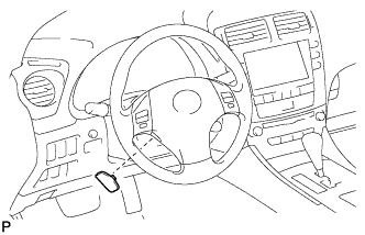
- HINT:
- Tape up the screwdriver tip before use.
| 19. REMOVE LOWER NO. 2 STEERING WHEEL COVER |
Using a screwdriver, remove the steering wheel No.2 cover lower.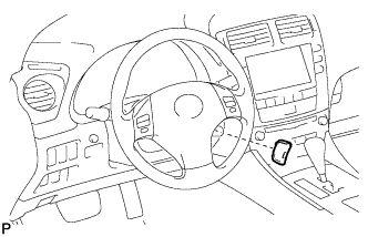
- HINT:
- Tape up the screwdriver tip before use.
| 20. REMOVE STEERING PAD |
Using a "torx" socket wrench (T30), loosen the 2 "torx" screws until the groove along the screw circumference catches on the screw case.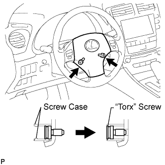
Pull out the steering pad from the steering wheel assembly and support the steering pad with one hand as shown in the illustration.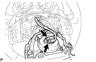
- NOTICE:
- When removing the steering pad, do not pull the airbag wire harness.
Disconnect the horn connector.
Disconnect the 2 connectors from the steering pad.
- NOTICE:
- When handling the airbag connector, take care not to damage the airbag wire harness.
Remove the steering pad.
| 21. REMOVE STEERING WHEEL ASSEMBLY |
Remove the steering wheel assembly set nut.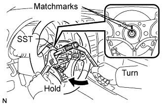
Put matchmarks on the steering wheel assembly and main shaft assembly.
Using SST, remove the steering wheel assembly.
- SST
- 09950-50013
(09951-05010, 09952-05010, 09953-05020, 09954-05011)
| 22. REMOVE STEERING COLUMN COVER (for Power Tilt and Power Telescopic) |
Remove the 3 screws.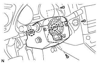
Disengage the 2 claws to remove the steering column cover lower.
- NOTICE:
- Do not damage the tilt and telescopic switch.
Disengage the 4 clips to separate the steering column cover upper.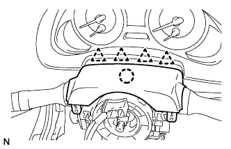
Disengage the claw to remove the steering column cover upper.
| 23. REMOVE STEERING COLUMN COVER (for Manual Tilt and Telescopic) |
Remove the 2 screws.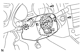
Disengage the 2 claws to remove the lower steering column cover.
Disengage the 4 clips to separate the steering column cover upper.
Disengage the claw to remove the upper steering column cover.
| 24. REMOVE TURN SIGNAL SWITCH ASSEMBLY WITH SPIRAL CABLE SUB-ASSEMBLY |
Disconnect the connectors from the turn signal switch assembly with spiral cable sub-assembly.
Using pliers, grip the claws of the clip and remove the turn signal switch assembly with spiral cable sub-assembly from the steering column assembly.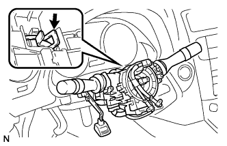
| 25. REMOVE FRONT DOOR SCUFF PLATE LH (w/o Illumination) |
Put protective tape around the front door scuff plate.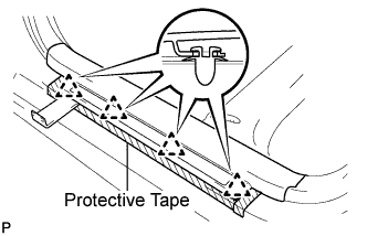
Using a moulding remover, disengage the 4 clips.
Disengage the 7 claws and remove the front door scuff plate LH.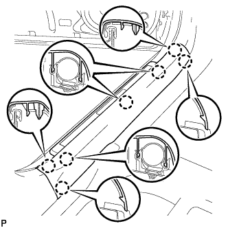
| 26. REMOVE FRONT DOOR SCUFF PLATE LH (w/ Illumination) |
Put protective tape around the front door scuff plate.
Using a moulding remover, disengage the 4 clips.
Disengage the 7 claws and remove the front door scuff plate LH.
Disconnect the connector.
| 27. REMOVE FRONT DOOR OPENING TRIM COVER LH |
Disengage the 6 claws and remove the front door opening trim cover LH.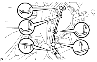
| 28. REMOVE SIDE INSTRUMENT PANEL LH |
Using a moulding remover, disengage the 5 claws and 3 clips, and then remove the side instrument panel LH.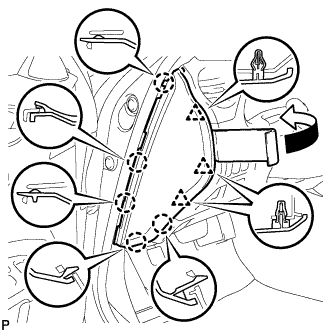
| 29. REMOVE NO. 1 INSTRUMENT PANEL UNDER COVER SUB-ASSEMBLY |
Remove the 2 screws <E>.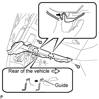
Push the 2 claws in the direction indicated by the arrow to disengage them.
Remove the No. 1 instrument panel under cover sub-assembly from the guide as shown in the illustration and pull the cover toward the rear of the vehicle.
Disconnect the connectors and remove the No. 1 instrument panel under cover sub-assembly.
| 30. REMOVE LOWER INSTRUMENT PANEL FINISH PANEL SUB-ASSEMBLY |
Disengage the 7 clips.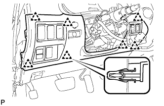
Disconnect the connectors and remove the lower instrument panel finish panel sub-assembly.
| 31. REMOVE DRIVER SIDE KNEE AIRBAG ASSEMBLY |
Remove the 4 bolts and driver side knee airbag assembly.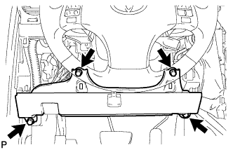
Disconnect the connector.
- NOTICE:
- When handling the airbag connector, take care not to damage the airbag wire harness.
| 32. REMOVE INSTRUMENT CLUSTER FINISH PANEL SUB-ASSEMBLY |
Remove the 2 screws <G> and 2 clips, and then remove the instrument cluster finish panel sub-assembly.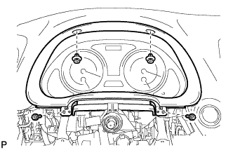
| 33. REMOVE COMBINATION METER ASSEMBLY |
Using a screwdriver, disengage the 2 claws.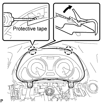
- HINT:
- Tape the screwdriver tip before use.
Disconnect the connectors and remove the combination meter assembly.
| 34. REMOVE FRONT DOOR SCUFF PLATE RH (w/o Illumination) |
| 35. REMOVE FRONT DOOR SCUFF PLATE RH (w/ Illumination) |
| 36. REMOVE FRONT DOOR OPENING TRIM COVER RH |
Disengage the 6 claws and remove the front door opening trim cover RH.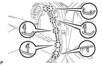
| 37. REMOVE SIDE INSTRUMENT PANEL RH |
Using a moulding remover, disengage the 5 claws and 3 clips, and then remove the side instrument panel RH.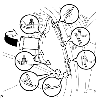
| 38. REMOVE NO. 2 INSTRUMENT PANEL UNDER COVER SUB-ASSEMBLY |
Using a moulding remover, disengage the 4 clips and remove the No. 2 instrument panel under cover sub-assembly.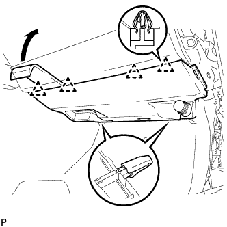
| 39. REMOVE FRONT PASSENGER SIDE KNEE AIRBAG ASSEMBLY |
Remove the 3 bolts and front passenger side knee airbag assembly.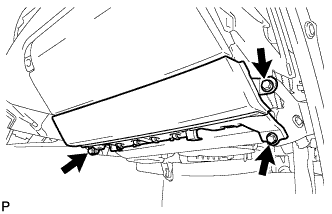
Disconnect the connector.
- NOTICE:
- When handling the airbag connector, take care not to damage the airbag wire harness.
| 40. REMOVE GLOVE COMPARTMENT DOOR ASSEMBLY |
Remove the 5 screws <E>.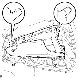
Disengage the 2 claws.
Disconnect the connectors and remove the glove compartment door assembly.
| 41. REMOVE FRONT PILLAR GARNISH LH |
Disengage the 2 clips from the vehicle body.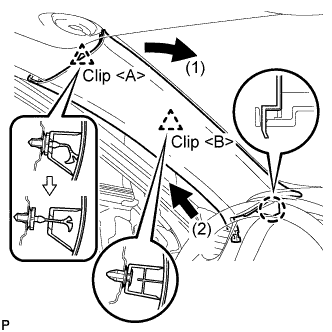
Cut off the clip <A>.
Disengage the claw and remove the front pillar garnish LH.
Remove the clip <A> from the vehicle body.
Protect the curtain shield airbag assembly.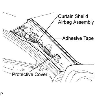
Thoroughly cover the airbag with a cloth or nylon sheet and fix the ends of the cover with adhesive tape, as shown in the illustration.
- NOTICE:
- Cover the curtain shield airbag with a protective cover as soon as the front pillar garnish is removed.
| 42. REMOVE FRONT PILLAR GARNISH RH |
| 43. REMOVE NO. 1 INSTRUMENT PANEL REGISTER ASSEMBLY |
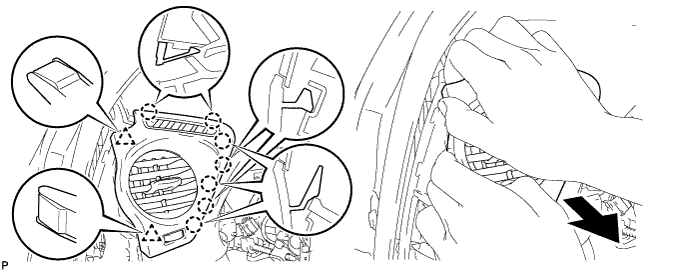
Pull the No. 1 instrument panel register assembly in the direction indicated by the arrow to disengage the 7 claws and 2 clips, and then disconnect the connector and remove it.
| 44. REMOVE NO. 2 INSTRUMENT PANEL REGISTER ASSEMBLY |
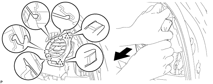
Pull the No. 2 instrument panel register assembly in the direction indicated by the arrow to disengage the 4 claws and 2 clips, and then disconnect the connector and remove it.
| 45. REMOVE NO. 3 INSTRUMENT PANEL SPEAKER PANEL SUB-ASSEMBLY |
Using a screwdriver, disengage the 7 claws and remove the No. 3 instrument panel speaker panel sub-assembly.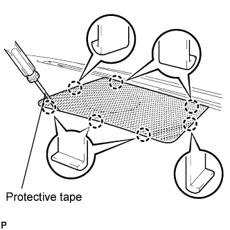
- HINT:
- Tape the screwdriver tip before use.
| 46. REMOVE FRONT STEREO COMPONENT SPEAKER ASSEMBLY |
Remove the 2 bolts.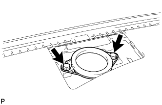
Lift the front stereo component speaker assembly and disconnect the connector to remove the speaker assembly.
- NOTICE:
- Do not touch the cone part of the speaker.
| 47. REMOVE NO. 2 CONSOLE BOX DUCT (for Automatic Transmission) |
Remove the 2 clips and No. 2 console box duct.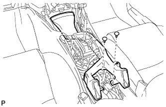
| 48. REMOVE NO. 1 CONSOLE BOX DUCT (for Automatic Transmission) |
Remove the clip and No. 1 console box duct.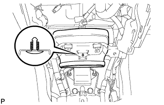
| 49. REMOVE NO. 2 CONSOLE BOX DUCT (for Manual Transmission) |
Remove the clip and No. 2 console box duct.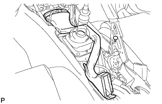
| 50. DISCONNECT PASSENGER AIRBAG CONNECTOR |
| 51. REMOVE INSTRUMENT PANEL SAFETY PAD ASSEMBLY |
Disengage the clamps.
Disconnect the connectors.
Disengage the 2 claws and separate the cooler thermistor.
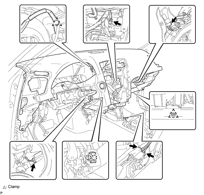
Remove the 6 bolts <D> and nut <H>.
Remove the 2 passenger airbag bolts <A> or <B>.
Disengage the 2 clamps.
Disengage the 5 claws and remove the instrument panel safety pad assembly.

| 52. REMOVE NO. 2 ANTENNA CORD SUB-ASSEMBLY |
Disengage the clamp and remove the No. 2 antenna cord sub-assembly.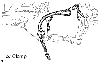
| 53. REMOVE REAR SEAT CUSHION ASSEMBLY |
Detach the 2 front hooks of the seat cushion from the vehicle body.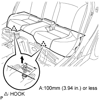
- NOTICE:
- Follow the instructions below carefully as the cushion frame deforms easily.
Choose a hook to detach first. Place your hands near the hook as shown in the illustration. Then lift the seat cushion to detach the hook.
Repeat for the other hook.
Detach the 2 rear hooks of the seat cushion from the seatback.
Remove the seat cushion.
| 54. REMOVE REAR SEAT HEADREST ASSEMBLY |
| 55. REMOVE REAR CENTER SEAT HEADREST ASSEMBLY |
| 56. REMOVE REAR SEATBACK ASSEMBLY |
Using a screwdriver, detach the claws to open the cap of the 3 rear seat shoulder belt guides.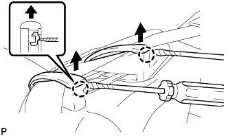
Using a screwdriver, detach the claw to open the cap of the 3 rear seat shoulder belt guides.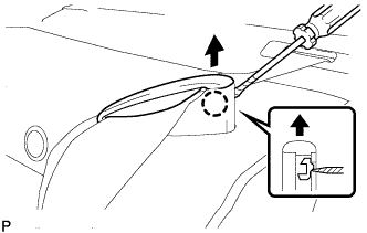
Remove the 4 bolts and rear seatback assembly.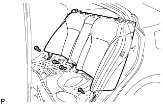
| 57. REMOVE REAR DOOR SCUFF PLATE |
- HINT:
- Removal procedure of the RH side is the same as that of the LH side (Click here).
| 58. REMOVE REAR SIDE SEAT GARNISH |
- HINT:
- Removal procedure of the RH side is the same as that of the LH side (Click here).
| 59. REMOVE ROOF SIDE INNER GARNISH |
- HINT:
- Removal procedure of the RH side is the same as that of the LH side (Click here).
| 60. REMOVE ANTENNA CORD SUB-ASSEMBLY (w/o DVD Player) |
Disconnect each connector.
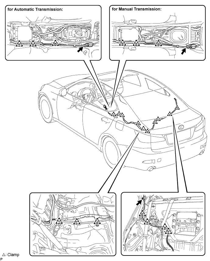
Remove the 3 bolts and disengage the 19 clamps.
Remove the antenna cord sub-assembly.
| 61. REMOVE LUGGAGE COMPARTMENT TRIM COVER (w/ DVD Player) |
| 62. REMOVE DECK SIDE TRIM BOX RH (w/ DVD Player) |
| 63. REMOVE DECK SIDE TRIM BOX LH (w/ DVD Player) |
| 64. REMOVE SPARE WHEEL COVER (w/ DVD Player) |
| 65. REMOVE ROPE HOOK ASSEMBLY (w/ DVD Player) |
Remove the 3 bolts and 3 rope hook assemblies.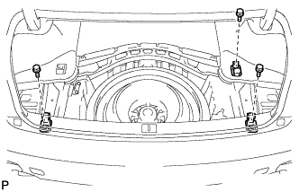
| 66. REMOVE REAR LUGGAGE COMPARTMENT TRIM COVER (w/ DVD Player) |
Using a clip remover, remove the 3 clips.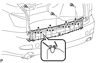
Disengage the 4 clips and remove the rear luggage compartment trim cover.
| 67. REMOVE ROOM LIGHT ASSEMBLY (w/ DVD Player) |
Disengage the claw and disconnect the No. 2 room light assembly.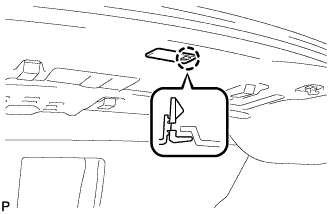
Disconnect the connector and remove the No. 2 room light assembly.
| 68. REMOVE ROPE HOOK (w/ DVD Player) |
Remove the 2 rope hooks.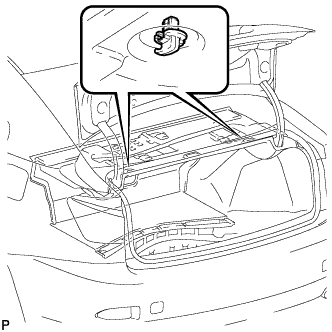
| 69. REMOVE FRONT LUGGAGE COMPARTMENT TRIM COVER (w/ DVD Player) |
Remove the 3 luggage compartment trim hooks as shown in the illustration.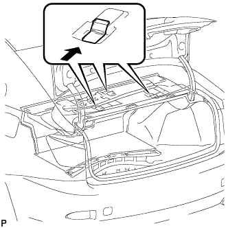
Using a clip remover, remove the 2 clips.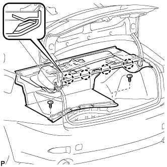
Disengage the 4 claws and remove the front luggage compartment trim cover.
| 70. REMOVE LUGGAGE COMPARTMENT TRIM HOOK (w/ DVD Player) |
Remove the screw and luggage compartment trim hook.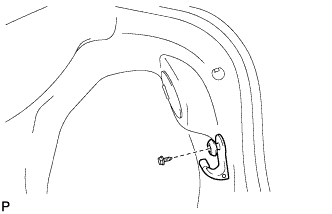
| 71. REMOVE SIDE LUGGAGE COMPARTMENT TRIM COVER (w/ DVD Player) |
Using a clip remover, remove the 3 clips and side luggage compartment trim cover.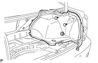
| 72. REMOVE ANTENNA CORD SUB-ASSEMBLY (w/ DVD Player) |
Disconnect the connectors.
Disengage the 3 clamps and separate the antenna cord.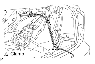
Disconnect each connector.
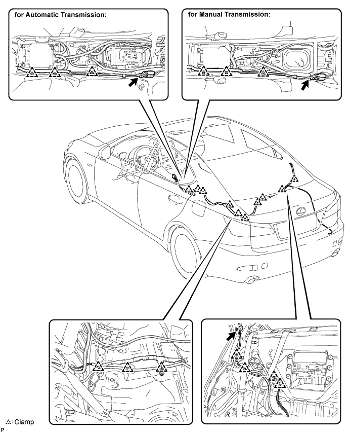
Remove the 3 bolts and disengage the 19 clamps.
Remove the antenna cord sub-assembly.