REMOVAL
Removal / installation
| 1. DISCONNECT CABLE FROM NEGATIVE BATTERY TERMINAL |

- CAUTION:
- Wait for 90 seconds after disconnecting the cable to prevent airbag deployment (Click here).
| 2. REMOVE STEERING COLUMN COVER (for Manual Tilt and Telescopic) |
The steering wheel assembly is turned to the right and remove the screw as shown in the illustration.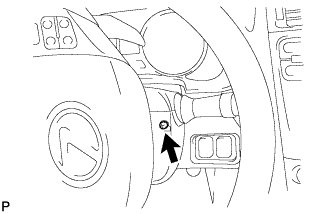

The steering wheel assembly is turned to the left and remove the screw as shown in the illustration.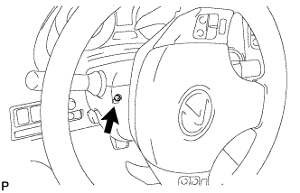
Disengage the 2 claws and remove the steering column cover lower.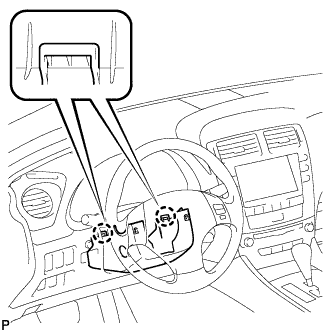
Disengage the 4 clips and 3 claws to remove the steering column cover upper.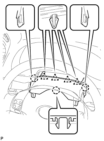
| 3. REMOVE STEERING COLUMN COVER (for Power Tilt and Power Telescopic) |
The steering wheel assembly is turned to the right and remove the screw as shown in the illustration.
The steering wheel assembly is turned to the left and remove the screw as shown in the illustration.
Disengage the 2 claws and remove the screw and the steering column cover lower.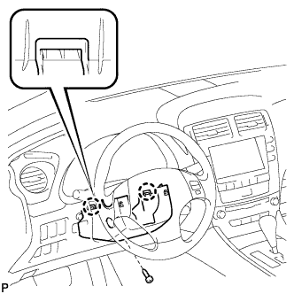
Disengage the 4 clips and 3 claws to remove the steering column cover upper.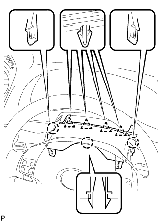
| 4. REMOVE FRONT DOOR SCUFF PLATE LH (w/o Illumination) |
Put protective tape around the front door scuff plate.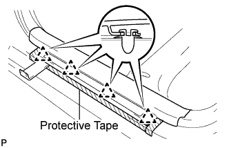
Using a moulding remover, disengage the 4 clips.
Disengage the 7 claws and remove the front door scuff plate LH.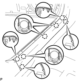
| 5. REMOVE FRONT DOOR SCUFF PLATE LH (w/ Illumination) |
Put protective tape around the front door scuff plate.
Using a moulding remover, disengage the 4 clips.
Disengage the 7 claws and remove the front door scuff plate LH.
Disconnect the connector.
| 6. REMOVE FRONT DOOR OPENING TRIM COVER LH |
Disengage the 6 claws and remove the front door opening trim cover LH.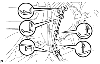
| 7. REMOVE SIDE INSTRUMENT PANEL LH |
Using a moulding remover, disengage the 5 claws and 3 clips, and then remove the side instrument panel LH.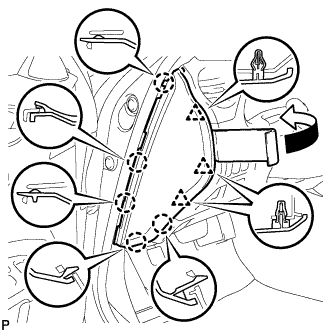
| 8. REMOVE LOWER INSTRUMENT PANEL FINISH PANEL SUB-ASSEMBLY |
Disengage the 7 clips.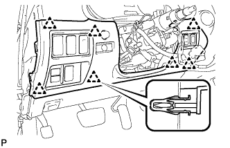
Disconnect the connectors and remove the lower instrument panel finish panel sub-assembly.
| 9. REMOVE INSTRUMENT CLUSTER FINISH PANEL SUB-ASSEMBLY |
Disengage the 2 clips.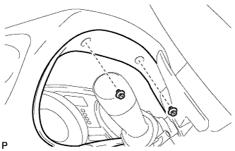
Remove the 2 screws and remove the instrument cluster finish panel sub-assembly.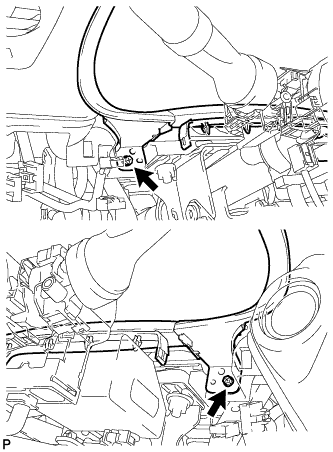
| 10. REMOVE WINDSHIELD WIPER SWITCH ASSEMBLY |
Disconnect the 2 connectors.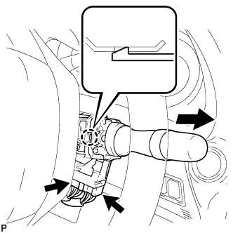
Disengage the claw and remove the windshield wiper switch assembly as shown in the illustration.
- NOTICE:
- If the claw is pushed with excessive force, it may break.
| 11. REMOVE COMBINATION METER ASSEMBLY |
Attach protective tape to the position indicated in the illustration.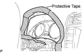
Using a screwdriver, disengage the claw.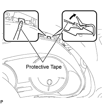
- HINT:
- Tape the screwdriver tip before use.
Using a screwdriver, disengage the claw, and pull out the combination meter assembly.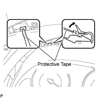
- HINT:
- Tape the screwdriver tip before use.
Disconnect the connectors and remove the combination meter assembly as shown in the illustration.
- NOTICE:
- Do not damage the instrument panel safety pad or combination meter assembly when removing the combination meter assembly.
| 12. REMOVE COMBINATION METER GLASS |
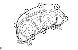
Disengage the 9 claws and remove the combination meter glass.