REASSEMBLY
Removal / installation
| 1. INSTALL COOLER EVAPORATOR SUB-ASSEMBLY |

Sufficiently apply compressor oil to 2 new O-rings and the fitting surface of the cooler evaporator sub-assembly.
- Compressor oil:
- ND-OIL 8 or equivalent
Install the 2 O-rings on the cooler evaporator sub-assembly.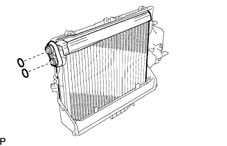

Install the air duct with the 3 claws and 5 screws.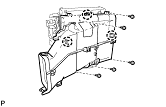
| 2. INSTALL HEATER RADIATOR UNIT SUB-ASSEMBLY |
Install the heater radiator unit sub-assembly.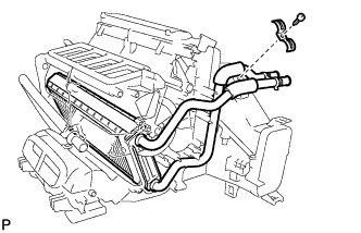
Install the clamp with the screw.
| 3. INSTALL AIR OUTLET CONTROL SERVO MOTOR |
Install the air outlet control servo motor with the 2 screws.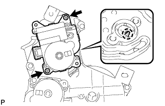
Temporarily install the drive gear to the air outlet control servomotor. Check that the drive gear and the driven gear are engaged at point with the same number of gear teeth from the standard position. Install the drive gear to the air outlet control servomotor.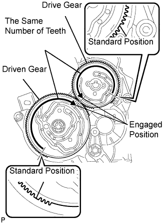
- NOTICE:
- If there is not the same number of gear teeth from the standard position on each gear at the point where the two gears are engaged, remove the drive gear, adjust the driven gear, and reinstall the drive gear.
- The number of gear teeth from the standard position varies according to the stop position of the air outlet control servomotor. Make sure that the gears are engaged at a point with the same number of gear teeth from the standard position.
- If there is not the same number of gear teeth from the standard position on each gear at the point where the two gears are engaged, the air outlet control servo motor may not operate normally.
- If there is not the same number of gear teeth from the standard position on each gear at the point where the two gears are engaged, remove the drive gear, adjust the driven gear, and reinstall the drive gear.
| 4. INSTALL AIR MIX CONTROL SERVO MOTOR |
Install the air mix control servo motor with the 2 screws.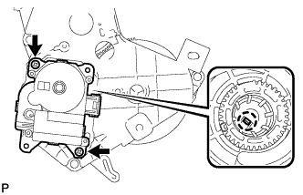
Install the drive gear to the air mix control servo motor.
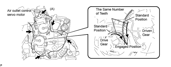
Temporarily install the mode damper servo assembly so that the levers fit into each groove.
Slightly lift the air outlet control servo motor. Check that the drive gear and the driven gear are engaged at a point with the same number of gear teeth from the standard position from the view indicated by arrow (A).
- NOTICE:
- If there is not the same number of gear teeth from the standard position on each gear at the point where the two gears are engaged, lift the air outlet control servo motor to adjust the driven gear and reinstall the air outlet control servo motor.
- If there is not the same number of gear teeth from the standard position on each gear at the point where the two gears are engaged, the air outlet control servo motor may not operate normally.
- If there is not the same number of gear teeth from the standard position on each gear at the point where the two gears are engaged, lift the air outlet control servo motor to adjust the driven gear and reinstall the air outlet control servo motor.
Install the air outlet control servo motor with the 4 screws.
| 5. INSTALL AIR CONDITIONING HARNESS ASSEMBLY |
Attach the 4 clamps to install the air conditioning harness assembly.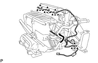
Install the air conditioning harness as shown in the illustration.
Connect the 2 connectors and attach the clamp.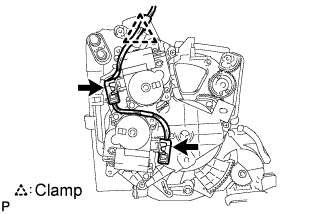
| 6. INSTALL COOLER EXPANSION VALVE |
Install the expansion valve.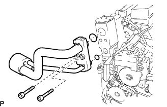
Sufficiently apply compressor oil to 2 new O-rings and the fitting surface of the air conditioning tube assembly.
- Compressor oil:
- ND-OIL 8 or equivalent
Install the 2 O-rings on the air conditioning tube assembly.
Using a hexagon wrench 4 mm, install the air conditioning tube assembly with the 2 hexagon bolts.
- Torque:
- 3.5 N*m{ 35 kgf*cm , 30 in.*lbf }
Install a new packing.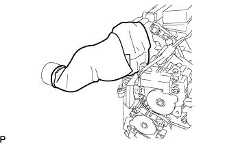
| 7. INSTALL AIR MIX CONTROL SERVO MOTOR |
Check that the drive gear and the driven gear are engaged at a point with the same number of gear teeth from the standard position. Temporarily install the air mix control servo motor.
- NOTICE:
- If there is not the same number of gear teeth from the standard position on each gear at the point where the two gears are engaged, remove the air mix control servo motor to adjust the driven gear and reinstall the air mix control servo motor.
- The number of gear teeth from the standard position varies according to the stop position of the air mix control servo motor. Make sure that the gears are engaged at a point with the same number of gear teeth from the standard position.
- If there is not the same number of gear teeth from the standard position on each gear at the point where the two gears are engaged, the air mix control servo motor may not operate normally.
- If there is not the same number of gear teeth from the standard position on each gear at the point where the two gears are engaged, remove the air mix control servo motor to adjust the driven gear and reinstall the air mix control servo motor.
Install the air mix control servo motor with the 3 screws.
| 8. INSTALL AIR OUTLET CONTROL SERVO MOTOR |
Install the air outlet control servo motor with the 3 screws.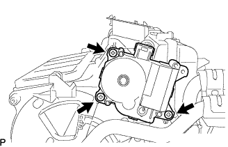
Connect the connector.