INSTALLATION
Removal / installation
| 1. INSTALL COOLER DRYER |

Using pliers, install the cooler dryer to the modulator.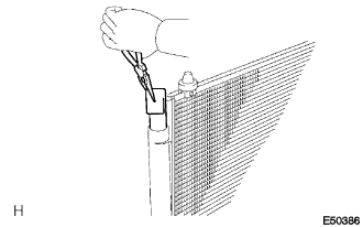

Sufficiently apply compressor oil to an O-ring and cap fitting surface.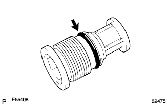
- Compressor oil:
- ND-OIL 8 or equivalent
Using a straight hexagon wrench 14 mm, install the cap to the cooler condenser core.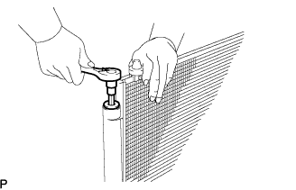
- Torque:
- 2.9 N*m{ 30 kgf*cm , 26 in.*lbf }
| 2. INSTALL COOLER CONDENSER ASSEMBLY |
Install the cooler condenser assembly with the 4 bolts.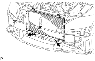
- Torque:
- 5.0 N*m{ 51 kgf*cm , 44 in.*lbf }
- HINT:
- If the condenser is replaced with a new one, add compressor oil to the new condenser.
- Capacity:
- 40 cc (1.4 fl. oz.)
- Compressor oil:
- ND-8 or equivalent
| 3. INSTALL DISCHARGE HOSE SUB-ASSEMBLY |
Remove the attached vinyl tape from the hose and the connecting part of the cooler condenser assembly.
Sufficiently apply compressor oil to a new O-ring and the fitting surface of the hose joint.
- Compressor oil:
- ND-OIL 8 or equivalent
Install the O-ring on the discharge hose sub-assembly.
Install the discharge hose sub-assembly on the cooler condenser assembly with the bolt.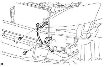
- Torque:
- 5.4 N*m{ 55 kgf*cm , 48 in.*lbf }
| 4. INSTALL LIQUID TUBE SUB-ASSEMBLY |
Remove the attached vinyl tape from the pipe and the connecting part of the cooler condenser assembly.
Sufficiently apply compressor oil to a new O-ring and the fitting surface of the pipe joint.
- Compressor oil:
- ND-OIL 8 or equivalent
Install the O-ring on the liquid tube sub-assembly.
Install the liquid tube sub-assembly on the cooler condenser assembly with the 2 bolts.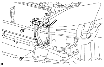
- Torque:
- 5.4 N*m{ 55 kgf*cm , 48 in.*lbf }
| 5. INSTALL RADIATOR SUPPORT UPPER |
Install the 5 bolts and the upper radiator support.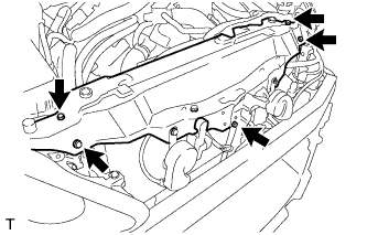
- Torque:
- 8.0 N*m{ 82 kgf*cm , 71 in.*lbf }
Install the 6 wire harness clamps and the No.2 engine room wire.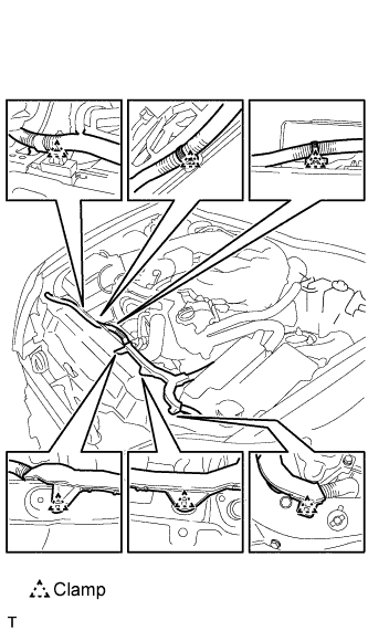
Connect the clamp and the No.2 cooling fan motor connector.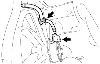
Connect the clamp and the cooling fan motor connector.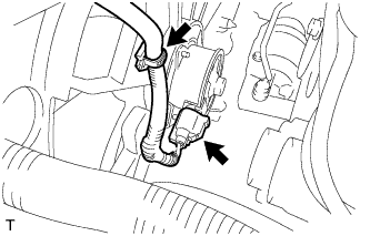
Connect the 4 wire harness clamps and the 3 connectors.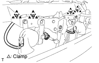
| 6. INSTALL HOOD LOCK ASSEMBLY |
Install the 2 bolts and the hood lock assembly to the upper radiator support.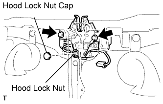
- Torque:
- 8.0 N*m{ 82 kgf*cm , 71 in.*lbf }
Install the hood lock nut and the hood lock nut cap.
- Torque:
- 8.0 N*m{ 82 kgf*cm , 71 in.*lbf }
Connect the connector.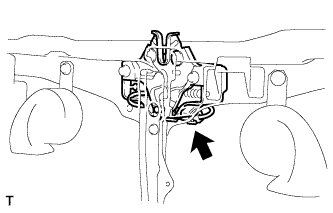
| 7. INSTALL HOOD LOCK CONTROL CABLE COVER |
RHD
Connect the clamp, and install the 3 screws and the hood lock control cable cover.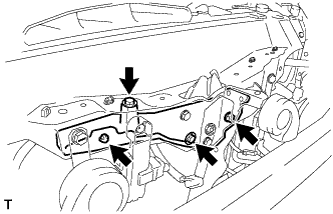
LHD
Connect the clamp, and install the 3 screws and the hood lock control cable cover.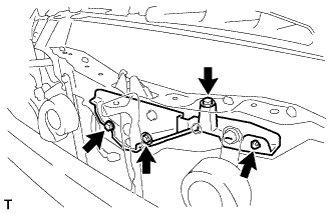
| 8. INSTALL MILLIMETER WAVE RADAR SENSOR ASSEMBLY (w/ Dynamic Radar Cruise Control System) |
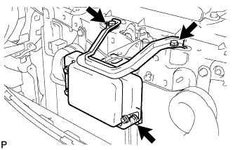 |
Install the millimeter wave radar sensor with the 3 bolts.
- Torque:
- 5.5 N*m{ 56 kgf*cm , 49 in.*lbf }
Connect the connector.
| 9. INSTALL RADIATOR SUPPORT OPENING COVER |
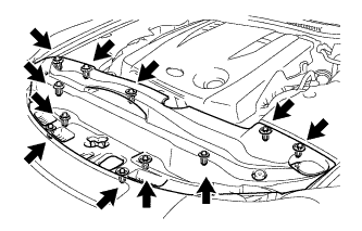
Connect the 2 clips, and install the radiator support opening cover.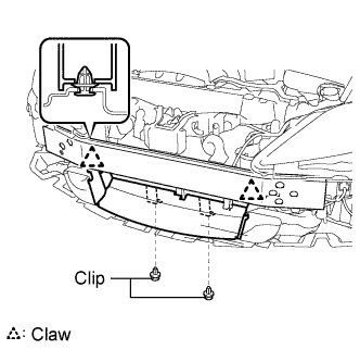
| 10. INSTALL FRONT BUMPER ENERGY ABSORBER |
| 11. INSTALL FRONT BUMPER ASSEMBLY |
| 12. INSTALL UNDER ENGINE COVER |
| 13. INSTALL NO. 1 INLET AIR CLEANER |
Install the inlet air cleaner with the bolt.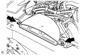
- Torque:
- 5.0 N*m{ 51 kgf*cm , 44 in.*lbf }
| 14. CHARGE REFRIGERANT |
Perform vacuum purging using a vacuum pump.
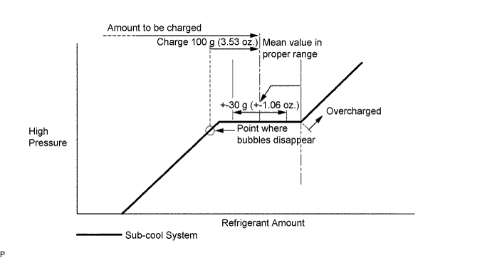
Charge refrigerant HFC-134a (R134a).
- Standard:
- 430 +- 30 g (15.17 +- 1.06 oz.)
- SST
- 07110-58060
(07117-58060, 07117-58070, 07117-58080, 07117-58090, 07117-78050, 07117-88060, 07117-88070, 07117-88080)
- NOTICE:
- Do not operate the cooler compressor before charging refrigerant as the cooler compressor will not work properly without any refrigerant, and will overheat.
- Do not operate the cooler compressor before charging refrigerant as the cooler compressor will not work properly without any refrigerant, and will overheat.
- Approximately 100 g (3.53 oz.) of refrigerant may need to be charged after bubbles disappear. The refrigerant amount should be checked by measuring its quantity, and not with the sight glass.
- Approximately 100 g (3.53 oz.) of refrigerant may need to be charged after bubbles disappear. The refrigerant amount should be checked by measuring its quantity, and not with the sight glass.
| 15. WARM UP ENGINE |
Warm up the engine at less than 1,850 rpm for 2 minutes or more after charging the refrigerant.
- NOTICE:
- Be sure to warm up the compressor when turning the A/C switch ON after removing and installing the cooler refrigerant lines (including the compressor), to prevent damage to the compressor.
| 16. CHECK FOR LEAKAGE OF REFRIGERANT |
After recharging the refrigerant gas, check for refrigerant gas leakage using a halogen leak detector.
Perform the operation under the following conditions:
- Stop the engine.
- Secure good ventilation (the gas leak detector may react to volatile gases other than refrigerant, such as evaporated gasoline or exhaust gas).
- Repeat the test 2 or 3 times.
- Make sure that some refrigerant remains in the refrigeration system. When compressor is off: approximately 392 to 588 kPa (4 to 6 kgf*cm2 57 to 85 psi)
- Stop the engine.
Using a gas leak detector, check the refrigerant line for leakage.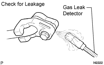
If a gas leak is not detected on the drain hose, remove the blower motor control (blower resistor) from the cooling unit. Insert the gas leak detector sensor into the unit and perform the test.
Disconnect the connector and leave the pressure switch on for approximately 20 minutes. Bring the gas leak detector close to the pressure switch and perform the test.
| 17. INSTALL V-BANK COVER SUB-ASSEMBLY |
Engage the 2 clips on the front of the cover, and then engage the clip on the rear to install the V-bank cover.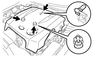
- NOTICE:
- Be sure to engage the clips securely.
- Do not apply excessive force or do not hit the cover to engage the clips. This may cause the cover to break.
- Be sure to engage the clips securely.
| 18. INSTALL SIDE ENGINE ROOM COVER LH |
Install the side cover with the 5 clips.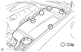
| 19. INSTALL SIDE ENGINE ROOM COVER RH |
Install the side cover with the 2 clips.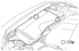
| 20. INSTALL COOL AIR INTAKE DUCT SEAL |
Install the intake duct seal with the 11 clips.