REMOVAL
Removal / installation
- NOTICE:
- When disassembling the clock assembly, eliminate static electricity by touching the vehicle body to prevent the components from being damaged.
| 1. REMOVE SHIFT LEVER KNOB SUB-ASSEMBLY (for Automatic Transmission) |

Turn the shift lever knob counterclockwise and remove the shift lever knob sub-assembly.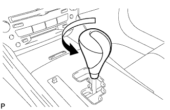

| 2. REMOVE SHIFT LEVER KNOB SUB-ASSEMBLY (for Manual Transmission) |
Turn the shift lever knob counterclockwise and remove the shift lever knob sub-assembly.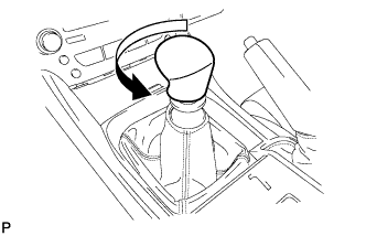
| 3. REMOVE UPPER NO. 1 CONSOLE PANEL GARNISH (for Automatic Transmission) |
Using a moulding remover, disengage the claw.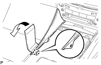
Pull the upper No. 1 console panel garnish in the direction indicated by the arrow to disengage the 2 clips and remove it.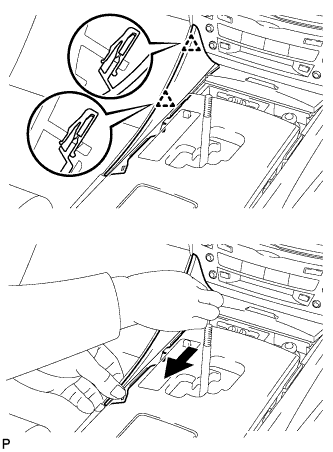
| 4. REMOVE UPPER NO. 2 CONSOLE PANEL GARNISH (for Automatic Transmission) |
Using a moulding remover, disengage the claw.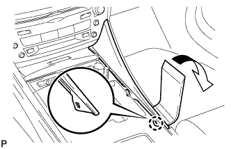
Pull the upper No. 2 console panel garnish in the direction indicated by the arrow to disengage the 2 clips and remove it.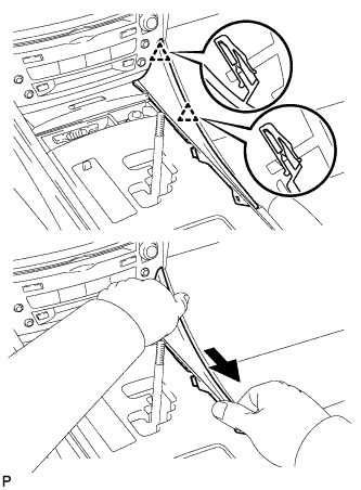
| 5. REMOVE CONSOLE PANEL SUB-ASSEMBLY (for Automatic Transmission) |
Disengage the 8 clips.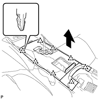
Disconnect the connectors and remove the console panel sub-assembly.
| 6. REMOVE REAR CONSOLE PANEL SUB-ASSEMBLY (for Manual Transmission) |
Open the snap.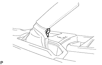
Disengage the 7 claws and 2 clips, and then remove the rear console panel sub-assembly.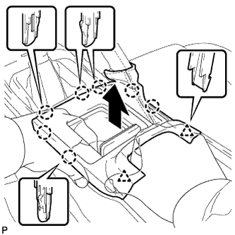
| 7. REMOVE FRONT CONSOLE PANEL SUB-ASSEMBLY (for Manual Transmission) |
Open the snap.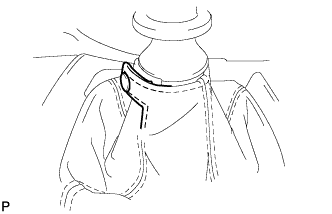
Pull the front console panel sub-assembly in the direction indicated by the arrow to disengage the 6 clips and remove it.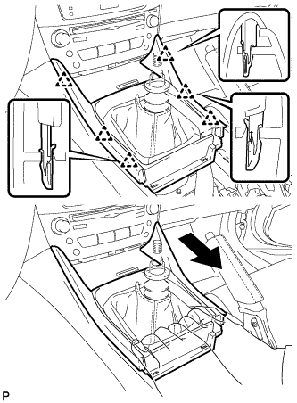
| 8. REMOVE FRONT ASH RECEPTACLE SUB-ASSEMBLY |
Remove the 2 screws <F>.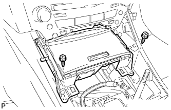
Pull the front ash receptacle sub-assembly in the direction indicated by the arrow to disconnect the connectors and remove it.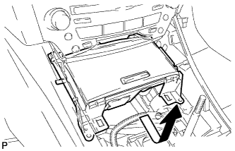
| 9. REMOVE CONSOLE BOX REGISTER ASSEMBLY |
Remove the rear ash receptacle assembly.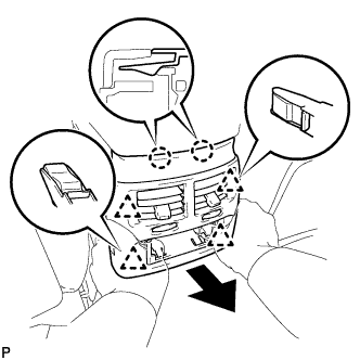
Disengage the 2 claws and 4 clips, and then remove the console box register assembly.
| 10. REMOVE CONSOLE BOX |
Remove the 2 bolts <C>.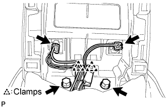
Disconnect the 2 connectors.
Disengage the 2 clamps.
Remove the 2 bolts <C>.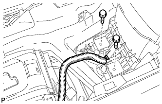
Disconnect the connector.
Remove the 2 bolts <C>.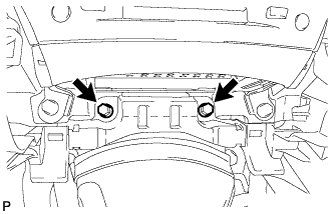
Disengage the 2 claws and 2 clips, and then remove the console box.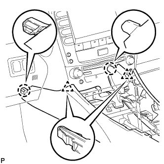
| 11. REMOVE NO. 3 INSTRUMENT PANEL REGISTER ASSEMBLY |
Using a screwdriver, disengage the 4 claws.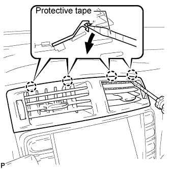
- HINT:
- Tape the screwdriver tip before use.
Apply protective tape to the areas shown in the illustration.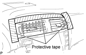
Using a moulding remover, disengage the 4 claws starting from the right of the No. 3 instrument panel register assembly. Disengage the remaining 3 claws by pulling the No. 3 instrument panel register assembly by hand.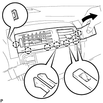
- NOTICE:
- Do not pry the lower part of the No. 3 instrument panel register assembly. Doing so may damage the assembly.
Disconnect the connectors.
| 12. REMOVE CENTER LOWER INSTRUMENT CLUSTER FINISH PANEL |
Disengage the 4 claws and remove the center lower instrument cluster finish panel.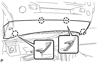
| 13. REMOVE INTEGRATION CONTROL PANEL WITH RADIO RECEIVER ASSEMBLY (w/o Navigation System) |
Remove the 4 bolts.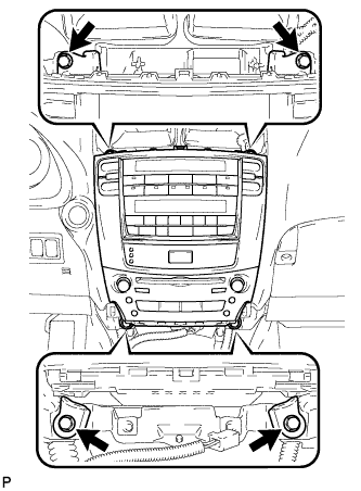
Pull the integration control panel w/ radio receiver assembly toward the rear of the vehicle.
Disconnect each connector and remove the panel.
| 14. REMOVE NO. 1 RADIO BRACKET (w/o Navigation System) |
Remove the 6 bolts and radio No. 1 bracket.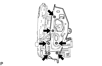
| 15. REMOVE NO. 2 RADIO BRACKET (w/o Navigation System) |
Remove the 6 bolts and radio No. 2 bracket.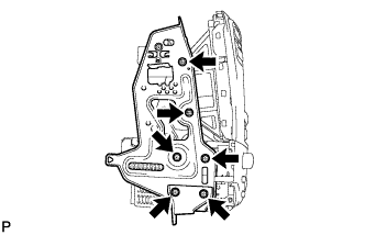
| 16. REMOVE RADIO RECEIVER ASSEMBLY (w/o Navigation System) |
Slide the integration control panel in the direction shown by the arrow to remove the radio receiver assembly.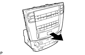
| 17. REMOVE CLOCK ASSEMBLY (w/o Navigation System) |
Remove the 6 screws.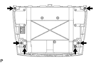
Disengage the 5 claws and integration control panel.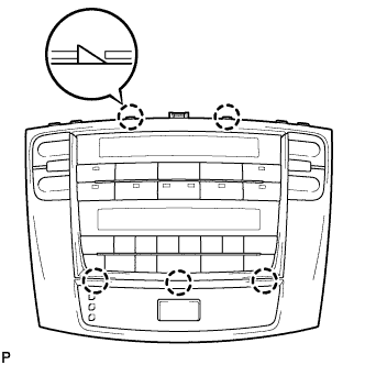
Remove the 9 screws and cover.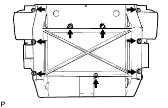
Disconnect the connectors.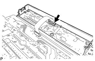
Remove the clock assembly.
| 18. REMOVE MULTI-DISPLAY ASSEMBLY (w/ Navigation System) |
Remove the 4 bolts.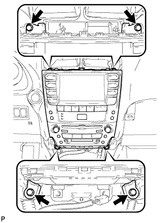
Pull the multi-display w/ radio receiver assembly toward the rear of the vehicle.
Disconnect each connector and remove the multi-display.
| 19. REMOVE NO. 1 RADIO BRACKET (w/ Navigation System) |
Disengage the connector clamp.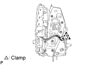
Remove the 7 bolts and radio No. 1 bracket.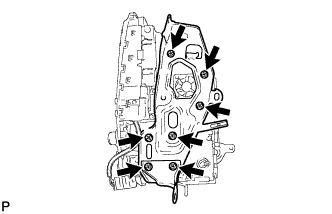
| 20. REMOVE NO. 2 RADIO BRACKET (w/ Navigation System) |
Remove the 7 bolts and radio No. 2 bracket.
| 21. REMOVE RADIO RECEIVER ASSEMBLY (w/ Navigation System) |
Slide the multi-display in the direction shown by the arrow to remove the radio receiver assembly.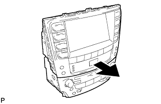
| 22. REMOVE CLOCK ASSEMBLY (w/ Navigation System) |
Apply protective tape to the places shown in the illustration.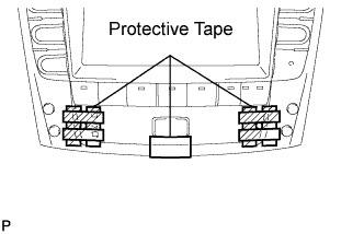
Insert 2 precision screwdrivers (φ1.5 or less) into the holes on both sides of the clock assembly at the angle as shown in the illustration.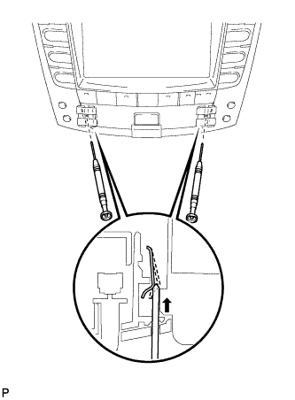
- NOTICE:
- Do not pry on the clock assembly with the screwdrivers as it may damage the clock assembly.
- HINT:
- If precision screwdrivers are not available, use in-vehicle tools (part No. 09135-53010).
Insert a screwdriver with its tip taped from the underside of the hazard switch, and pull and remove the clock assembly.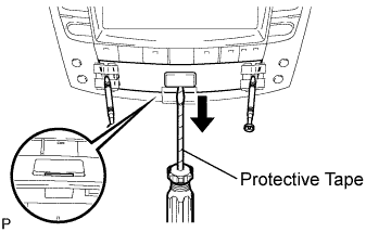
- NOTICE:
- Do not pry on the hazard switch with the screwdriver as it may damage the switch.