INSPECTION
Inspection
| INSPECT REAR DOOR LOCK LH ASSEMBLY |

INSPECT UNLOCK DETECTION SWITCH
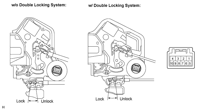

Remove the rear door lock assembly LH.
Measure the resistance according to the value(s) in the table below.
- Standard resistance:
Tester Connection
Measurement Condition
Door Lock Condition
(Specified Condition)
6 - 9 (*1)
Battery positive (+) → Terminal 2
Battery negative (-) → Terminal 1
Lock
10 kΩ or higher
6 - 9 (*1)
Battery positive (+) → Terminal 1
Battery negative (-) → Terminal 2
Unlock
Below 1 Ω
6 - 9 (*2)
Battery positive (+) → Terminal 4
Battery negative (-) → Terminal 1
Lock
10 kΩ or higher
6 - 9 (*2)
Battery positive (+) → Terminal 1
Battery negative (-) → Terminal 4
Unlock
Below 1 Ω
*2: w/o Double locking system
INSPECT REAR DOOR LOCK MOTOR
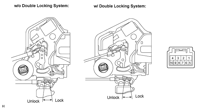
Apply battery voltage and check operation of the door lock motor.
- OK:
Measurement Condition
Specified Condition
Battery positive (+) → Terminal 4
Battery negative (-) → Terminal 1 (*1)
Lock
Battery positive (+) → Terminal 1
Battery negative (-) → Terminal 4 (*1)
Unlock
Battery positive (+) → Terminal 2
Battery negative (-) → Terminal 1 (*2)
Lock
Battery positive (+) → Terminal 1
Battery negative (-) → Terminal 2 (*2)
Unlock
*2: w/o Double locking system
INSPECT DOUBLE LOCK POSITION SWITCH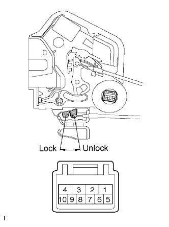
Remove the rear door lock assembly LH.
Apply battery voltage and set the door lock motor to the lock position.
- OK:
Measurement Condition
Specified Condition
Battery positive (+) →Terminal 2
Battery negative (-) →Terminal 1
Lock
Apply battery voltage to the door lock and check operation of the double lock motor.
- OK:
Measurement Condition
Specified Condition
Battery positive (+) →Terminal 4
Battery negative (-) →Terminal 3
Double Locking System is set
Battery positive (+) →Terminal 3
Battery negative (-) →Terminal 4
Double Locking System is unset
Measure the resistance according to the value(s) in the table below.
- Standard resistance:
Tester Connection
Double Lock Position
Specified Condition
9 - 10
Set
Below 1 Ω
9 - 10
Unset
10 kΩ or higher
INSPECT DOUBLE DOOR LOCK MOTOR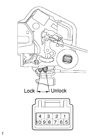
Remove the rear door lock assembly LH.
Apply battery voltage and set the door lock motor to the lock position.
- OK:
Measurement Condition
Specified Condition
Battery positive (+) →Terminal 2
Battery negative (-) →Terminal 1
Lock
Apply battery voltage to the door lock and check operation of the double lock motor.
- OK:
Measurement Condition
Specified Condition
Battery positive (+) →Terminal 4
Battery negative (-) →Terminal 3
Double Locking System is set
Battery positive (+) →Terminal 3
Battery negative (-) →Terminal 4
Double Locking System is unset
Check that the doors cannot be unlocked by operating the control cable while the double locking system is set.
- OK:
- The doors cannot be unlocked.
| INSPECT REAR DOOR LOCK RH ASSEMBLY |
INSPECT UNLOCK DETECTION SWITCH
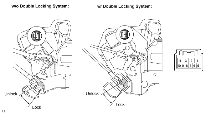
Remove the rear door lock assembly RH.
Measure the resistance according to the value(s) in the table below.
- Standard resistance:
Tester Connection
Measurement Condition
Door Lock Condition
(Specified Condition)
9 - 10 (*1)
Battery positive (+) → Terminal 4
Battery negative (-) → Terminal 1
Lock
10 kΩ or higher
9 - 10 (*1)
Battery positive (+) → Terminal 1
Battery negative (-) → Terminal 4
Unlock
Below 1 Ω
6 - 9 (*2)
Battery positive (+) → Terminal 4
Battery negative (-) → Terminal 1
Lock
10 kΩ or higher
6 - 9 (*2)
Battery positive (+) → Terminal 1
Battery negative (-) → Terminal 4
Unlock
Below 1 Ω
*2: w/o Double locking system
INSPECT REAR DOOR LOCK MOTOR
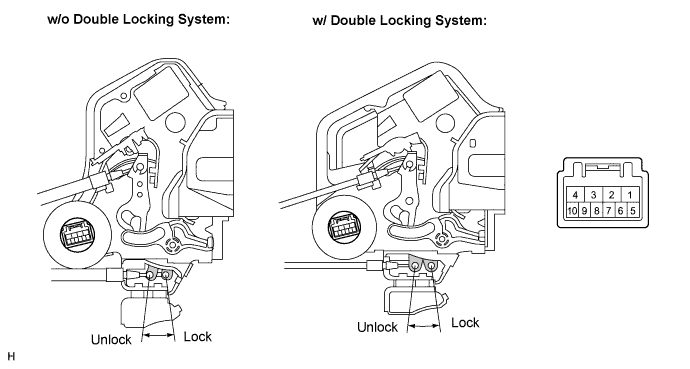
Remove the rear lock assembly RH.
Apply battery voltage and check operation of the door lock motor.
- OK:
Measurement Condition
Specified Condition
Battery positive (+) → Terminal 4
Battery negative (-) → Terminal 3 (*1)
Lock
Battery positive (+) → Terminal 3
Battery negative (-) → Terminal 4 (*1)
Unlock
Battery positive (+) → Terminal 4
Battery negative (-) → Terminal 1 (*2)
Lock
Battery positive (+) → Terminal 1
Battery negative (-) → Terminal 4 (*2)
Unlock
*2: w/o Double locking system
INSPECT DOUBLE LOCK POSITION SWITCH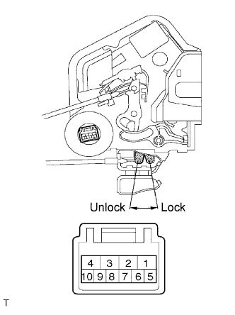
Apply battery voltage and set the door lock motor to the lock position.
- OK:
Measurement Condition
Specified Condition
Battery positive (+) →Terminal 4
Battery negative (-) →Terminal 3
Lock
Apply battery voltage to the door lock and check operation of the double lock motor.
- OK:
Measurement Condition
Specified Condition
Battery positive (+) →Terminal 2
Battery negative (-) →Terminal 1
Double Locking System is set
Battery positive (+) →Terminal 1
Battery negative (-) →Terminal 2
Double Locking System is unset
Measure the resistance according to the value(s) in the table below.
- Standard resistance:
Tester Connection
Double Lock Position
Specified Condition
5 - 6
Set
Below 1 Ω
5 - 6
Unset
10 kΩ or higher
INSPECT DOUBLE DOOR LOCK MOTOR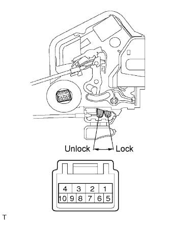
Apply battery voltage and set the door lock motor to the lock position.
- OK:
Measurement Condition
Specified Condition
Battery positive (+) →Terminal 4
Battery negative (-) →Terminal 3
Lock
Apply battery voltage to the door lock and check operation of the double lock motor.
- OK:
Measurement Condition
Specified Condition
Battery positive (+) →Terminal 2
Battery negative (-) →Terminal 1
Double Locking System is Set
Battery positive (+) →Terminal 1
Battery negative (-) →Terminal 2
Double Locking System is Unset
heck that the doors cannot be unlocked by operating the control cable while the double locking system is set.
- OK:
- The doors cannot be unlocked.