B1242
Diagnostic trouble codes
DESCRIPTION
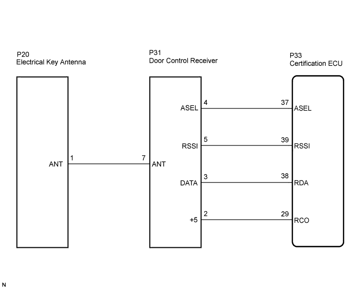
- The electrical key antenna and the door control receiver are used as antennas for the entry and wireless door lock functions of the entry and start system.
- The certification ECU decodes the requested entry and start system operation by identifying a key code based on electric waves received via the electrical key antenna and the door control receiver. The ECU then sends a command, according to the requested operation, to each ECU. (e.g. If door lock operation is requested, the ECU sends a door lock command to the main body ECU RH.)
DTC No.
DTC Detection Condition
Trouble Area
B1242
If the certification ECU detects that terminal RDA or RSSI is short-circuited, this DTC is stored.
- Electrical Key Antenna
- Door Control Receiver
- Wire harness
- Certification ECU
- Electrical Key Antenna
WIRING DIAGRAM

INSPECTION PROCEDURE
| 1. CHECK HARNESS AND CONNECTOR (CERTIFICATION ECU - DOOR CONTROL RECEIVER) |

Disconnect the P33 ECU connector.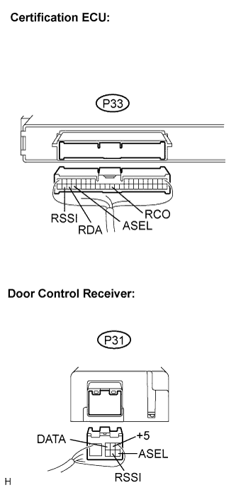
Disconnect the P31 receiver connector.
Measure the resistance according to the value(s) in the table below.
- Standard resistance:
Tester Connection (Symbols)
Condition
Specified Condition
P33-37 (ASEL) - P31-4 (ASEL)
Always
Below 1 Ω
P33-39 (RSSI) - P31-5 (RSSI)
Always
Below 1 Ω
P33-38 (RDA) - P31-3 (DATA)
Always
Below 1 Ω
P33-29 (RCO) - P31-2 (+5)
Always
Below 1 Ω
P33-37 (ASEL) - Body ground
Always
10 kΩ or higher
P33-39 (RSSI) - Body ground
Always
10 kΩ or higher
P33-38 (RDA) - Body ground
Always
10 kΩ or higher
P33-29 (RCO) - Body ground
Always
10 kΩ or higher
|
|
||||

| OK | |
 |
| 2. CHECK HARNESS AND CONNECTOR (DOOR CONTROL RECEIVER - ELECTRICAL KEY ANTENNA) |
Disconnect the P20 antenna connector.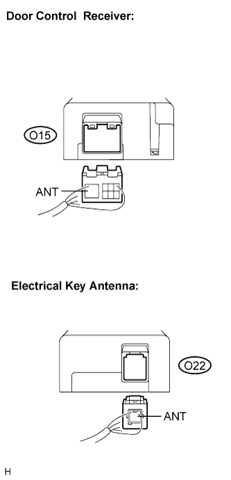
Measure the resistance according to the value(s) in the table below.
- HINT:
- Perform the measurement with the P31 receiver connector disconnected.
- Standard resistance:
Tester Connection
(Symbols)
Condition
Specified Condition
P31-7 (ANT) - P20-1 (ANT)
Always
Below 1 Ω
P31-7 (ANT) - Body ground
Always
10 kΩ or higher
|
|
||||
| OK | |
|
| 3. CHECK AND REPLACE DOOR CONTROL RECEIVER (RECONFIRM DTC) |
Replace the receiver.
Clear the DTC and repeat the procedure to re-check for DTCs (Click here).
- OK:
- DTC is not output.
|
|
||||
| NG | |
|
| 4. CHECK AND REPLACE ELECTRICAL KEY ANTENNA (RECONFIRM DTC) |
Replace the antenna.
Clear the DTC and repeat the procedure to re-check for DTCs (Click here).
- OK:
- DTC is not output.
|
|
||||
| NG | |
|
| 5. INSPECT CERTIFICATION ECU |
Reconnect the P33 ECU connector.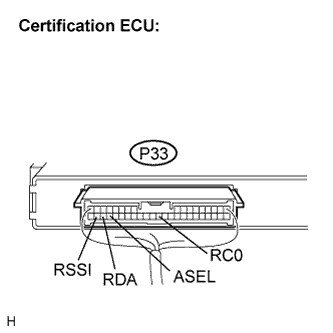
Reconnect the P20 antenna connector.
Reconnect the P31 receiver connector.
Measure the voltage according to the value(s) in the table below.
- Standard voltage:
Tester Connection
(Symbols)
Condition
Specified Condition
P33-37 (ASEL) - Body ground
Engine switch OFF, luggage compartment door OPEN
Below 1 V
Engine switch OFF, luggage compartment door CLOSE
4.6 to 5.4 V
P33-39 (RSSI) - Body ground
Engine switch OFF, all doors closed, the electrical key is not in the action area
10 to 14 V
Engine switch OFF, all doors closed, the electrical key in the action area
Below 1 V
P33-38 (RDA) -Body ground
Engine switch OFF, all doors closed and electrical key switch OFF
10 to 14 V
Engine switch OFF, all doors closed and electrical key switch ON
Pulse generation
P33-29 (RCO) - Body ground
Engine switch OFF, all doors closed and electrical key switch OFF
Below 1 V
Engine switch OFF, all doors closed and electrical key switch ON
4.6 to 5.4 V
|
|
||||
| OK | ||
 |
||
| ||