Door Oscillator Circuit
Circuit diagnosis
DESCRIPTION
Door oscillators are built into each door. Each of them forms its own action area around its door and detects the presence of the electrical key.WIRING DIAGRAM
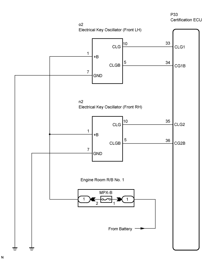

INSPECTION PROCEDURE
| 1. INSPECT ELECTRICAL KEY OSCILLATOR |

Disconnect the oscillator connectors.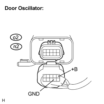
Measure the voltage according to the value(s) in the table below.
- Standard voltage:
- Front LH side:
Tester Connection (Symbols)
Condition
Specified Condition
o2-1 (+B) - o2-7 (GND)
Always
10 to 14 V
- Front RH side:
Tester Connection (Symbols)
Condition
Specified Condition
n2-1 (+B) - n2-7 (GND)
Always
10 to 14 V
|
|
||||

| OK | |
 |
| 2. CHECK HARNESS AND CONNECTOR (ELECTRICAL KEY OSCILLATOR - CERTIFICATION ECU) |
Disconnect the P33 ECU connector.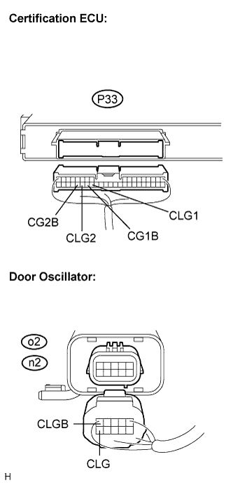
- Standard resistance:
Tester Connection (Symbols)
Condition
Specified Condition
P33-33 (CLG1) - o2-10 (CLG)
Always
Below 1 Ω
P33-34 (CG1B) - o2-5 (CLGB)
Always
Below 1 Ω
P33-35 (CLG2) - n2-10 (CLG)
Always
Below 1 Ω
P33-36 (CG2B) - n2-5 (CLGB)
Always
Below 1 Ω
P33-33 (CLG1) - Body ground
Always
10 kΩ or higher
P33-34 (CG1B) - Body ground
Always
10 kΩ or higher
P33-35 (CLG2) - Body ground
Always
10 kΩ or higher
P33-36 (CG2B) - Body ground
Always
10 kΩ or higher
|
|
||||
| OK | |
|
| 3. CHECK AND REPLACE ELECTRICAL KEY OSCILLATOR (CHECK OPERATION OF OSCILLATOR) |
Replace the door oscillator.
Check that the entry LOCK / UNLOCK function operates normally.
- OK:
- Entry LOCK / UNLOCK function operates normally.
|
|
||||
| NG | |
|
| 4. PERFORM ACTIVE TEST BY INTELLIGENT TESTER (CERTIFICATION ECU OUTPUT SIGNAL) |
Reconnect the ECU and the oscillator connectors.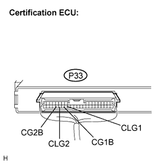
Connect the intelligent tester to the DLC3.
Turn the engine switch on (IG).
Following the display on the tester, select the "ACTIVE TEST".
SMART KEY (Certification ECU): Item
Vehicle Condition/Test Details
D Transmitter
Door Oscillator ON / OFF
P Transmitter
Door Oscillator ON / OFF
Measure the frequency according to the value(s) in the table below.
- Standard:
Tester Connection (Symbols)
Condition
Specified condition
P33-33 (CLG1) - P33-34 (CG1B)
During ACTIVE TEST
Frequency is generated (higher than 0 Hz)
P33-35 (CLG2) - P33-36 (CG2B)
During ACTIVE TEST
Frequency is generated (higher than 0 Hz)
|
|
||||
| OK | ||
 |
||
| ||