INSTALLATION
Removal / installation
| 1. INSTALL STOP LIGHT SWITCH ASSEMBLY |

Temporarily install the stop light switch assembly with the lock nut.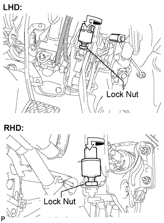

Turn the stop light switch assembly so that the clearance between the threaded area of the switch and the area where the pedal makes contact is between 0.5 and 2.4 mm (0.020 to 0.095 in. ). Fully tighten the lock nut.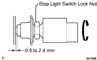
- Torque:
- 17 N*m{ 170 kgf*cm , 12 ft.*lbf }
Connect the connector to the stop light switch assembly.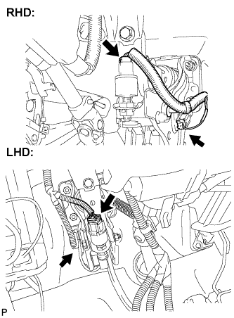
| 2. INSTALL DRIVER SIDE KNEE AIRBAG ASSEMBLY |
| 3. INSTALL LOWER INSTRUMENT PANEL FINISH PANEL SUB-ASSEMBLY |
Connect the connectors.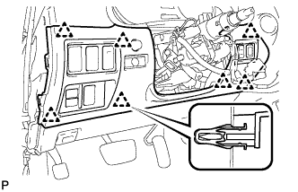
Engage the 7 clips and install the lower instrument panel finish panel sub-assembly.
| 4. INSTALL NO. 1 INSTRUMENT PANEL UNDER COVER SUB-ASSEMBLY |
Connect the connectors.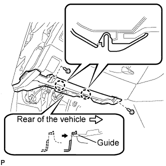
Insert the No. 1 instrument panel under cover sub-assembly into the guide as shown in the illustration.
Engage the 2 claws.
Install the No. 1 instrument panel under cover sub-assembly with the 2 screws <E>.
| 5. INSTALL INSTRUMENT SIDE PANEL LH (for LHD) |
Engage the 5 claws and 3 clips, and then install the side instrument panel LH.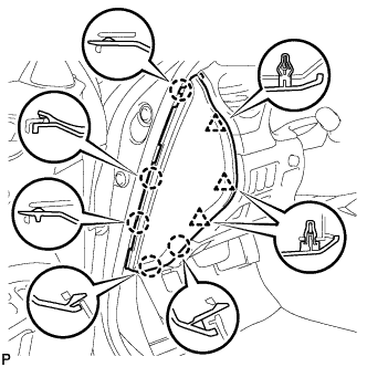
| 6. INSTALL INSTRUMENT SIDE PANEL RH (for RHD) |
Engage the 5 claws and 3 clips, and then install the side instrument panel RH.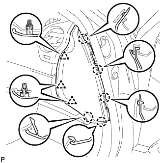
| 7. INSTALL FRONT DOOR OPENING TRIM COVER LH (for LHD) |
Engage the 6 claws and install the front door opening trim cover LH.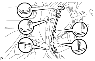
| 8. INSTALL FRONT DOOR OPENING TRIM COVER RH (for RHD) |
Engage the 6 claws and install the front door opening trim cover RH.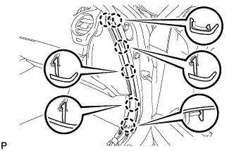
| 9. INSTALL FRONT DOOR SCUFF PLATE LH (for LHD) |
For w/ Illumination (Click here)
| 10. INSTALL FRONT DOOR SCUFF PLATE RH (for RHD) |
For w/ Illumination (Click here)
| 11. CONNECT BATTERY NEGATIVE TERMINAL |
| 12. INSPECT SRS WARNING LIGHT |
Inspect SRS warning light (Click here).
| 13. PERFORM INITIALIZATION |