REMOVAL
Removal / installation
| 1. DISCONNECT CABLE FROM NEGATIVE BATTERY TERMINAL |
| 2. REMOVE NO. 2 LUGGAGE COMPARTMENT TRIM COVER (w/ Clearance Sonar System) |
| 3. REMOVE SPARE WHEEL COVER (w/ Clearance Sonar System) |
| 4. REMOVE DECK SIDE TRIM BOX LH (w/ Clearance Sonar System) |
| 5. REMOVE DECK SIDE TRIM BOX RH (w/ Clearance Sonar System) |
| 6. REMOVE ROPE HOOK ASSEMBLY (w/ Clearance Sonar System) |

Remove the 3 bolts and 3 rope hook assemblies.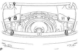

| 7. REMOVE REAR LUGGAGE COMPARTMENT TRIM COVER (w/ Clearance Sonar System) |
Using a clip remover, remove the 3 clips.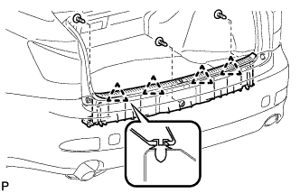
Disengage the 4 clips and remove the rear luggage compartment trim cover.
| 8. REMOVE NO. 2 ROOM LIGHT ASSEMBLY (w/ Clearance Sonar System) |
Disengage the claw and disconnect the No. 2 room light assembly.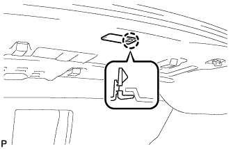
Disconnect the connector and remove the No. 2 room light assembly.
| 9. REMOVE ROPE HOOK (w/ Clearance Sonar System) |
Remove the 2 rope hooks.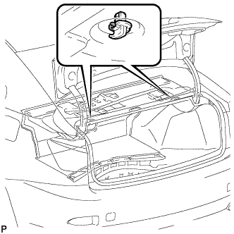
| 10. REMOVE FRONT LUGGAGE COMPARTMENT TRIM COVER (w/ Clearance Sonar System) |
Remove the 3 luggage compartment trim hooks as shown in the illustration.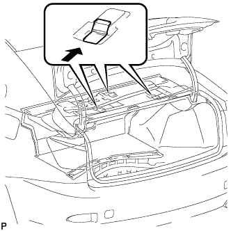
Using a clip remover, remove the 2 clips.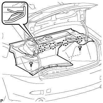
Disengage the 4 claws and remove the front luggage compartment trim cover.
| 11. REMOVE NO. 1 LUGGAGE COMPARTMENT TRIM HOOK (w/ Clearance Sonar System) |
Remove the screw and No. 1 luggage compartment trim hook.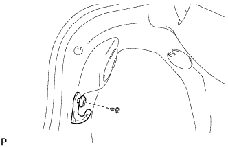
| 12. REMOVE SIDE LUGGAGE COMPARTMENT TRIM COVER LH (w/ Clearance Sonar System) |
Using a clip remover, remove the 3 clips and side luggage compartment trim cover LH.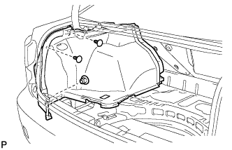
| 13. DISCONNECT NO. 3 LUGGAGE ROOM WIRE (w/ Clearance Sonar System) |
Disconnect the No. 3 luggage room wire connector.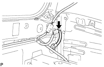
Disengage the grommet.
| 14. REMOVE NO. 1 REAR BUMPER PLATE |
Using a screwdriver, disengage the 2 claws and remove the No.1 rear bumper plate.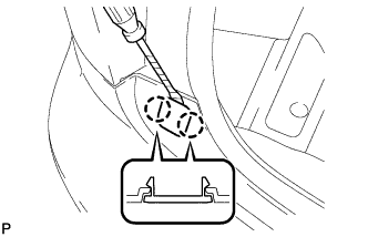
- HINT:
- Tape the screwdriver tip before use.
- Use the same procedures for the RH side and LH side.
- Tape the screwdriver tip before use.
| 15. REMOVE REAR BUMPER ASSEMBLY |
Put protective tape around the rear bumper assembly.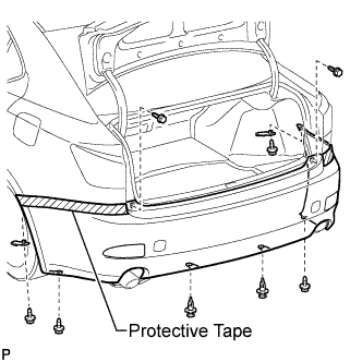
Using a clip remover, remove the 2 clips.
Remove the 6 screws and 2 rear bumper seal brackets.
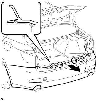
Disengage the 6 claws and disconnect the rear bumper assembly as shown in the illustration.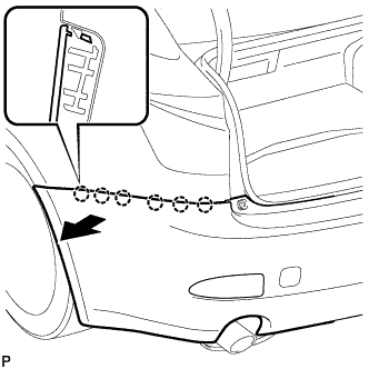
- HINT:
- Use the same procedures for the RH side and LH side.
Disengage the 4 claws and remove the rear bumper assembly as shown in the illustration.