Security Horn Circuit
Circuit diagnosis
DESCRIPTION
When the theft deterrent system is operating, the relay in the main body ECU RH turns on and off, causing the security horn to sound.WIRING DIAGRAM
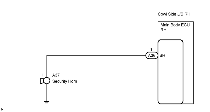

INSPECTION PROCEDURE
| 1. INSPECT SECURITY HORN ASSEMBLY |

Remove the security horn assembly.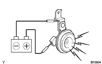
Check operation of the horn.
- Standard:
Measurement Condition
Specified Condition
Battery positive (+) → Terminal 1
Horn sounds
Battery negative (-) → Horn body
|
|
||||

| OK | |
 |
| 2. CHECK HARNESS AND CONNECTOR (MAIN BODY ECU RH (COWL SIDE J/B RH) - SECURITY HORN ASSEMBLY) |
Disconnect the A36 ECU connector and the A37 horn connector.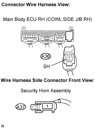
Measure the resistance according to the value(s) in the table below.
- Standard resistance:
Symbol (Terminal Connection)
Specified Condition
SH (A36-1) - (A37-1)
Below 1 Ω
SH (A36-1) or (A37-1) - Body ground
10 kΩ or higher
|
|
||||
| OK | ||
 |
||
| ||