INSTALLATION
Removal / installation
| 1. INSTALL NAVIGATION ECU |

Install the navigation ECU with the 4 bolts.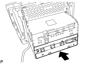

Connect the connectors.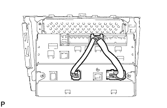
| 2. INSTALL MULTI-DISPLAY ASSEMBLY |
| 3. INSTALL NO. 2 RADIO BRACKET |
Install the radio No. 2 bracket with the 7 bolts.
| 4. INSTALL NO. 1 RADIO BRACKET |
Install the radio No. 1 bracket with the 7 bolts.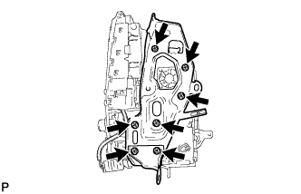
Engage the connector clamp.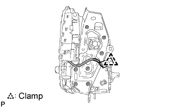
| 5. INSTALL MULTI-DISPLAY WITH RADIO RECEIVER ASSEMBLY |
Connect each connector.
Install the the multi-display w/ radio receiver assembly with the 4 bolts.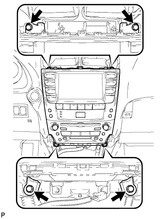
| 6. INSTALL CENTER LOWER INSTRUMENT CLUSTER FINISH PANEL |
Engage the 4 claws and install the center lower instrument cluster finish panel.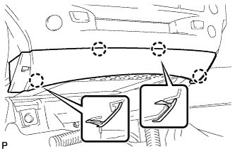
| 7. INSTALL NO. 3 INSTRUMENT PANEL REGISTER ASSEMBLY |
Connect the connectors.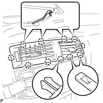
Engage the 11 claws and install the No. 3 instrument panel register assembly.
| 8. INSTALL CONSOLE BOX |
Engage the 2 claws and 2 clips.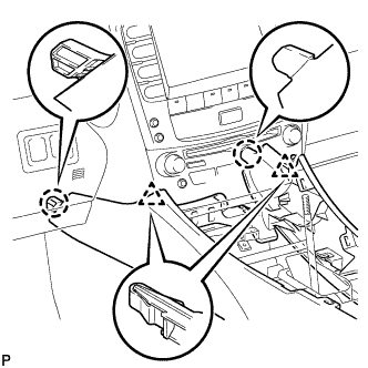
Install the 2 bolts <C>.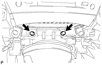
Install the 2 bolts <C>.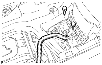
Connect the connector.
Connect the connectors.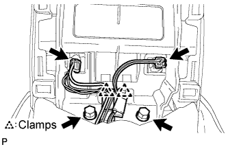
Engage the 2 clamps.
Install the 2 bolts <C>.
| 9. INSTALL CONSOLE BOX REGISTER ASSEMBLY |
Engage the 2 claws and 4 clips, and then install the console box register assembly.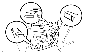
Install the rear ash receptacle assembly.
| 10. INSTALL FRONT ASH RECEPTACLE SUB-ASSEMBLY |
Connect the connectors.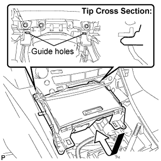
Insert the protruding parts of the front ash receptacle sub-assembly into the 2 guide holes as shown in the illustration.
Install the front ash receptacle sub-assembly with the 2 screws <F>.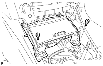
| 11. INSTALL FRONT CONSOLE PANEL SUB-ASSEMBLY (for Manual Transmission) |
Engage the 6 clips.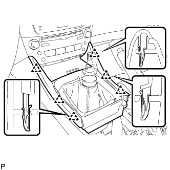
Close the snap.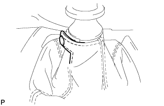
| 12. INSTALL REAR CONSOLE PANEL SUB-ASSEMBLY (for Manual Transmission) |
Engage the 7 claws and 2 clips.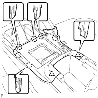
Close the snap.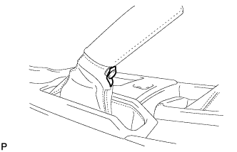
| 13. INSTALL CONSOLE PANEL SUB-ASSEMBLY (for Automatic Transmission) |
Connect the connectors.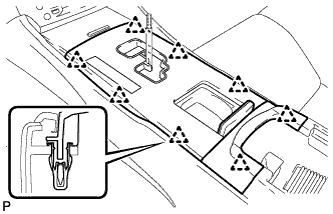
Engage the 8 clips and install the console panel sub-assembly.
| 14. INSTALL UPPER NO. 2 CONSOLE PANEL GARNISH (for Automatic Transmission) |
Engage the claw and 2 clips, and then install the upper No. 2 console panel garnish.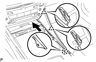
| 15. INSTALL UPPER NO. 1 CONSOLE PANEL GARNISH (for Automatic Transmission) |
Engage the claw and 2 clips, and then install the upper No. 1 console panel garnish.
| 16. INSTALL SHIFT LEVER KNOB SUB-ASSEMBLY (for Manual Transmission) |
| 17. INSTALL SHIFT LEVER KNOB SUB-ASSEMBLY (for Automatic Transmission) |
| 18. INSERT MAP DISC |
Remove the clock assembly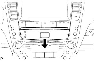
Turn the engine switch on (ACC).
Insert the map disc.
Check that the wire harness is in the position shown in the illustration.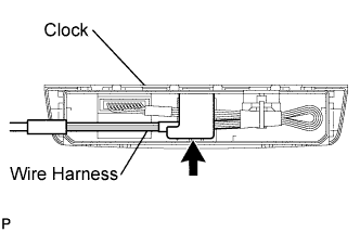
Install the clock assembly.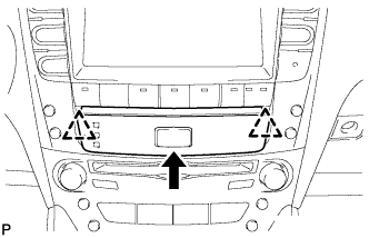
| 19. ADJUST CLOCK |