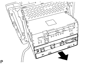
REMOVAL
Removal / installation
| 1. EJECT MAP DISC |

Turn the engine switch on (ACC).
Apply protective tape to the places shown in the illustration.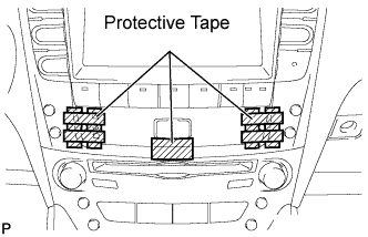

Insert 2 precision screwdrivers (φ1.5 or less) into the holes on both sides of the clock assembly at the angle shown in the illustration.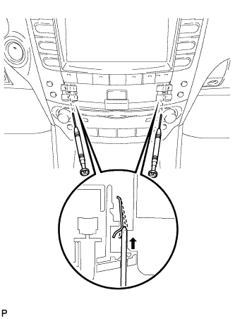
- NOTICE:
- Do not pry on the clock assembly with the screwdrivers as it may damage the clock assembly.
- HINT:
- If precision screwdrivers are not available, use in-vehicle tools (part No. 09135-53010).
Insert a protective taped screwdriver from the underside of the hazard switch and pull and remove the clock assembly.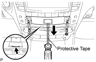
- NOTICE:
- Do not pry on the hazard switch with the screwdriver as it may damage the switch.
- Do not pry on the hazard switch with the screwdriver as it may damage the switch.
Remove the 2 precision screwdrivers.
Push the "MENU" button.
Touch "Map DVD" on the navigation screen.
Touch "EJECT DVD" on the navigation screen to eject the map disc.
Temporarily reinstall the clock assembly to make the removal of the multi-display assembly easier.
- NOTICE:
- Do not install the clock assembly completely because it will be removed later.
Turn the engine switch off.
| 2. REMOVE SHIFT LEVER KNOB SUB-ASSEMBLY (for Automatic Transmission) |
Turn the shift lever knob counterclockwise and remove the shift lever knob sub-assembly.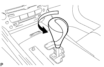
| 3. REMOVE SHIFT LEVER KNOB SUB-ASSEMBLY (for Manual Transmission) |
Turn the shift lever knob counterclockwise and remove the shift lever knob sub-assembly.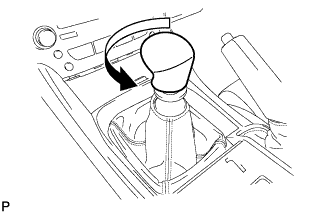
| 4. REMOVE UPPER NO. 1 CONSOLE PANEL GARNISH (for Automatic Transmission) |
Using a moulding remover, disengage the claw.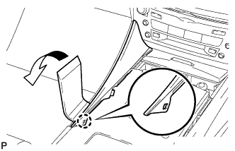
Pull the upper No. 1 console panel garnish in the direction indicated by the arrow to disengage the 2 clips and remove it.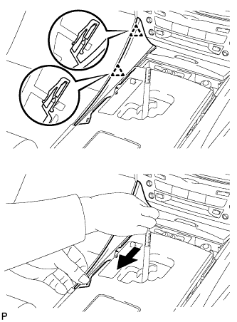
| 5. REMOVE UPPER NO. 2 CONSOLE PANEL GARNISH (for Automatic Transmission) |
Using a moulding remover, disengage the claw.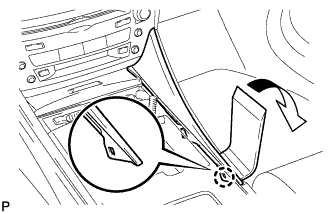
Pull the upper No. 2 console panel garnish in the direction indicated by the arrow to disengage the 2 clips and remove it.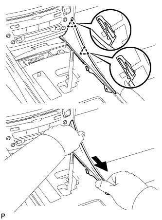
| 6. REMOVE CONSOLE PANEL SUB-ASSEMBLY (for Automatic Transmission) |
Disengage the 8 clips.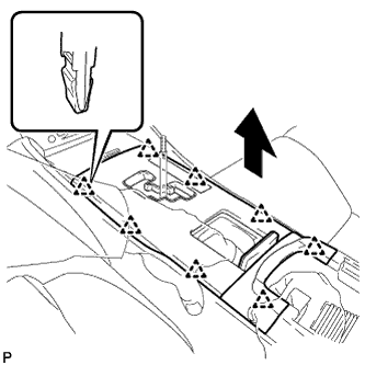
Disconnect the connectors and remove the console panel sub-assembly.
| 7. REMOVE REAR CONSOLE PANEL SUB-ASSEMBLY (for Manual Transmission) |
Open the snap.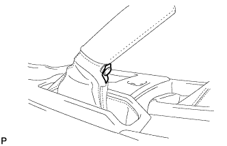
Disengage the 7 claws and 2 clips, and then remove the rear console panel sub-assembly.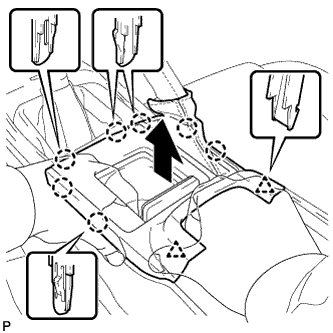
| 8. REMOVE FRONT CONSOLE PANEL SUB-ASSEMBLY (for Manual Transmission) |
Open the snap.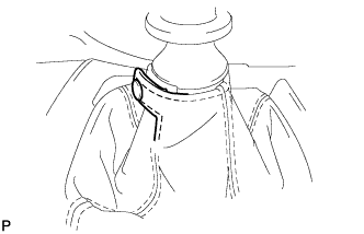
Pull the front console panel sub-assembly in the direction indicated by the arrow to disengage the 6 clips and remove it.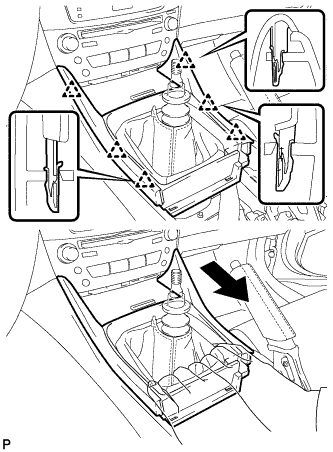
| 9. REMOVE FRONT ASH RECEPTACLE SUB-ASSEMBLY |
Remove the 2 screws <F>.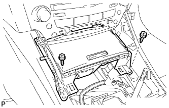
Pull the front ash receptacle sub-assembly in the direction indicated by the arrow to disconnect the connectors and remove it.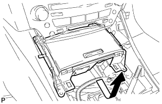
| 10. REMOVE CONSOLE BOX REGISTER ASSEMBLY |
Remove the rear ash receptacle assembly.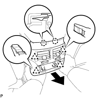
Disengage the 2 claws and 4 clips, and then remove the console box register assembly.
| 11. REMOVE CONSOLE BOX |
Remove the 2 bolts <C>.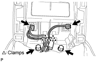
Disconnect the 2 connectors.
Disengage the 2 clamps.
Remove the 2 bolts <C>.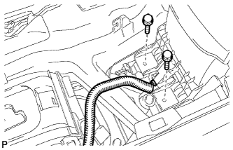
Disconnect the connector.
Remove the 2 bolts <C>.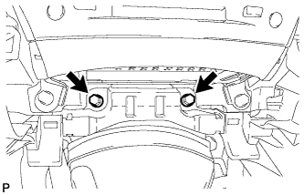
Disengage the 2 claws and 2 clips, and then remove the console box.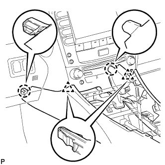
| 12. REMOVE NO. 3 INSTRUMENT PANEL REGISTER ASSEMBLY |
Using a screwdriver, disengage the 4 claws.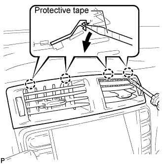
- HINT:
- Tape the screwdriver tip before use.
Apply protective tape to the areas shown in the illustration.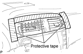
Using a moulding remover, disengage the 4 claws starting from the right of the No. 3 instrument panel register assembly. Disengage the remaining 3 claws by pulling the No. 3 instrument panel register assembly by hand.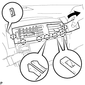
- NOTICE:
- Do not pry the lower part of the No. 3 instrument panel register assembly. Doing so may damage the assembly.
Disconnect the connectors.
| 13. REMOVE CENTER LOWER INSTRUMENT CLUSTER FINISH PANEL |
Disengage the 4 claws and remove the center lower instrument cluster finish panel.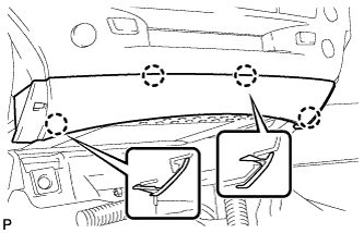
| 14. REMOVE MULTI-DISPLAY WITH RADIO RECEIVER ASSEMBLY |
Remove the 4 bolts.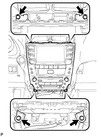
Pull the multi-display w/ radio receiver assembly toward the rear of the vehicle.
Disconnect each connector and remove the multi-display.
| 15. REMOVE NO. 1 RADIO BRACKET |
Disengage the connector clamp.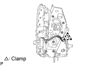
Remove the 7 bolts and radio No. 1 bracket.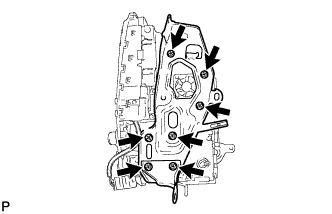
| 16. REMOVE NO. 2 RADIO BRACKET |
Remove the 7 bolts and radio No. 2 bracket.
| 17. REMOVE MULTI-DISPLAY ASSEMBLY |
Slide the multi-display in the direction shown by the arrow to remove the multi-display assembly.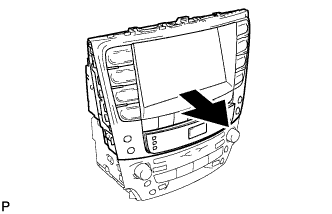
| 18. REMOVE NAVIGATION ECU |
Disconnect the connectors.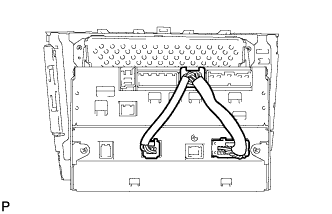
Remove the 4 bolts and navigation ECU.