TERMINALS OF ECU
System information
| CHECK MAIN BODY ECU RH (COWL SIDE J/B RH) |
Disconnect the main body ECU RH (cowl side J/B RH) connectors.
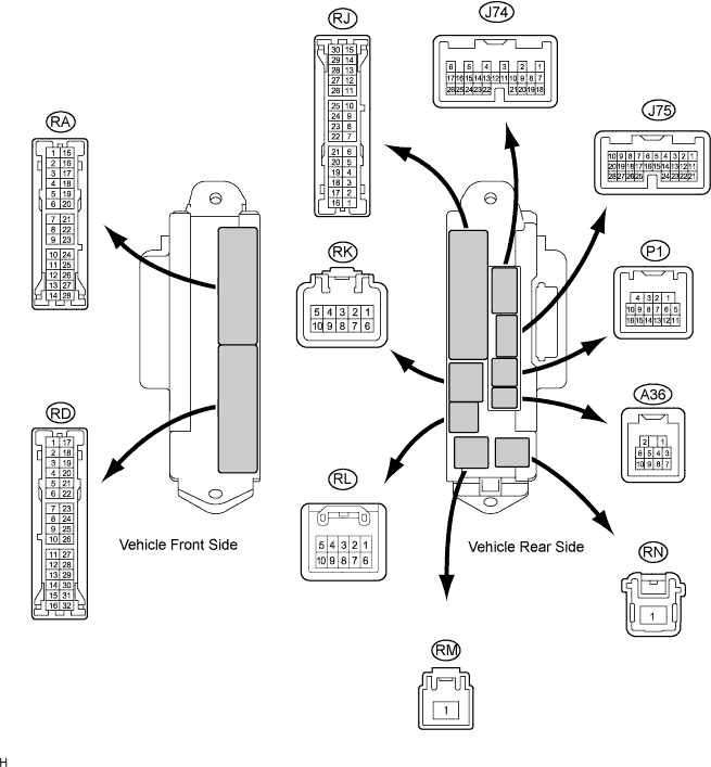

Measure the resistance and voltage of the wire harness side connectors.
Symbols (Terminal No.)
Wiring Color
Terminal Description
Condition
Specified Condition
PCTY (J75-23) - Body ground
B*1 - Body ground
Passenger side courtesy light switch input
Passenger side door CLOSED (OFF) → OPEN (ON)
10 kΩ or higher → Below 1 Ω
PCTY (J75-23) - Body ground
V*2- Body ground
Passenger side courtesy light switch input
Passenger side door CLOSED (OFF) → OPEN (ON)
10 kΩ or higher → Below 1 Ω
LGCY (J75-25) - Body ground
L - Body ground
Luggage compartment door courtesy light switch input
Luggage compartment door CLOSED (OFF) → OPEN (ON)
10 kΩ or higher → Below 1 Ω
DCTY (P1-14) - Body ground
W - Body ground
Driver side door courtesy light switch input
Driver side door CLOSED (OFF) → OPEN (ON)
10 kΩ or higher → Below 1 Ω
RCTY (P1-16) - Body ground
O - Body ground
Rear courtesy light switch RH input
Rear door RH CLOSED (OFF) → OPEN (ON)
10 kΩ or higher → Below 1 Ω
GND2 (RA-5) - Body ground
W-B - Body ground
Ground
Always
Below 1 Ω
LCTY (RA-11) - Body ground
BR - Body ground
Rear courtesy light switch LH input
Rear door LH CLOSED (OFF) → OPEN (ON)
10 kΩ or higher → Below 1 Ω
GND2 (RD-7) - Body ground
W-B - Body ground
Ground
Always
Below 1 Ω
BECU (RK-5) - Body ground
G-R - Body ground
+B power supply
Always
10 to 14 V
IG (RM-1) - Body ground
B - Body ground
Ignition power supply (IG signal)
Engine switch on (IG) → off
10 to 14 V → Below 1 V
- HINT:
- *1: LHD
- *2: RHD
Reconnect the main body ECU RH (cowl side J/B RH) connectors.
Measure the resistance and voltage of the wire harness side connectors.
Symbols (Terminal No.)
Wiring Color
Terminal Description
Condition
Specified Condition
SH (A36-1) - Body ground
W- Body ground
Security horn drive
Answer back security horn is not sounding → Sounding
Below 1 V → 10 to 14 V
BZR* (A36-2) - Body ground
G - Body ground
Wireless door lock buzzer
Wireless doo lock buzzer OFF → ON
0 V → Pulse generation
TR+ (J74-1) - Body ground
P - Body ground
Luggage compartment door opener motor input
Luggage compartment door CLOSED (LOCKED) → OPEN (UNLOCKED)
Below 1 V → 10 to 14 V
HAZ (J74-2) - Body ground
Y - Body ground
Turn signal flasher relay signal
Any transmitter switch is pressed → not pressed
Below 1 V → 10 to 14 V
- HINT:
- *: Australia, New Zealand
| CHECK CERTIFICATION ECU ASSEMBLY |
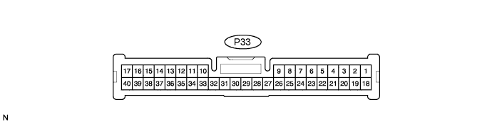
Disconnect the P33 ECU connector.
Measure the voltage and resistance of the wire harness side connector.
Symbols (Terminal No.)
Wiring Color
Terminal Description
Condition
Specified Condition
+B1 (P33-1) - E (P33-17)
L - W-B
Battery power supply
Always
10 to 14 V
E (P33-17) - Body ground
W-B - Body ground
Ground
Always
Below 1 Ω
IG (P33-18) - E (P33-17)
B - W-B
IG power supply
Engine switch on (IG)
10 to 14 V
IG (P33-18) - E (P33-17)
B - W-B
IG power supply
Engine switch off
Below 1 V
- If the result is not as specified, there may be a malfunction on the wire harness side.
- If the result is not as specified, there may be a malfunction on the wire harness side.
Reconnect the P33 ECU connector.
Measure the voltage of the connector.
Symbols (Terminal No.)
Wiring Color
Terminal Description
Condition
Specified Condition
RC0 (P33-29) - E (P33-17)
Y - W-B
Door control receiver power supply
Engine switch off, all doors closed and transmitter switch not pressed
Below 1 V
RC0 (P33-29) - E (P33-17)
Y - W-B
Door control receiver power supply
Engine switch off, all doors closed and transmitter switch pressed
4.6 to 5.4 V
RDA (P33-38) - E (P33-17)
R - W-B
Door control receiver output signal
Engine switch off, all doors closed and transmitter switch not pressed
10 to 14 V
RDA (P33-38) - E (P33-17)
R - W-B
Door control receiver output signal
Engine switch off, all doors closed and transmitter switch pressed
Pulse generation
- If the result is not as specified, the ECU may have a malfunction.
- If the result is not as specified, the ECU may have a malfunction.