B1925/78
Diagnostic trouble codes
DESCRIPTION
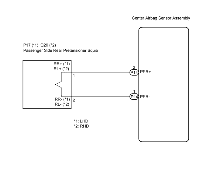
The passenger side rear pretensioner squib circuit consists of the center airbag sensor assembly and the rear seat outer belt assembly (passenger side).This circuit instructs the SRS to deploy when deployment conditions are met.
These DTCs are recorded when a malfunction is detected in the passenger side rear pretensioner squib circuit.
| DTC No. |
DTC Detection Condition |
Trouble Area |
| B1925/78 |
|
|
| B1926/78 |
|
|
| B1927/78 |
|
|
| B1928/78 |
|
|
WIRING DIAGRAM

INSPECTION PROCEDURE
- HINT:
- Perform the simulation method by selecting the "check mode" (signal check) with the intelligent tester (Click here).
- After selecting the "check mode" (signal check), perform the simulation method by wiggling each connector of the airbag system or driving the vehicle on a city or rough road (Click here).
- Perform the simulation method by selecting the "check mode" (signal check) with the intelligent tester (Click here).
| 1. CHECK REAR SEAT OUTER BELT ASSEMBLY (PASSENGER SIDE REAR PRETENSIONER SQUIB) |

Turn the engine switch off.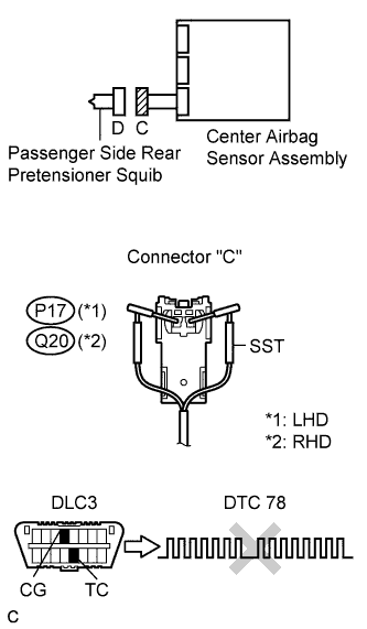
Disconnect the negative (-) terminal cable from the battery, and wait for at least 90 seconds.
Disconnect the connectors from the rear seat outer belt assembly (passenger side).
Connect the white wire side of SST (resistance 2.1 Ω) to connector "C".
- CAUTION:
- Never connect a tester to the rear seat outer belt assembly (passenger side rear pretensioner squib) for measurement, as this may lead to a serious injury due to airbag deployment.
- NOTICE:
- Do not forcibly insert the SST into the terminals of the connector when connecting.
- Insert straight the SST into the terminals of the connector.
- Do not forcibly insert the SST into the terminals of the connector when connecting.
Connect the negative (-) terminal cable to the battery, and wait for at least 2 seconds.
Turn the engine switch on (IG), and wait for at least 60 seconds.
Clear the DTCs stored in the memory (Click here).
Turn the engine switch off.
Turn the engine switch on (IG), and wait for at least 60 seconds.
Check for DTCs (Click here).
- OK:
- DTC B1925, B1926, B1927, B1928 or 78 is not output.
- HINT:
- Codes other than DTC B1925, B1926, B1927, B1928 and 78 may be output at this time, but they are not related to this check.
|
|
||||

| OK | |
 |
| 2. CHECK CONNECTOR |
Turn the engine switch off.
Disconnect the negative (-) terminal cable from the battery, and wait for at least 90 seconds.
Disconnect the SST from connector "C".
Check that the floor wire connector (on the rear seat outer belt assembly (passenger side) side) is not damaged.
|
|
||||
| OK | |
|
| 3. CHECK FLOOR WIRE (PASSENGER SIDE REAR PRETENSIONER SQUIB CIRCUIT) |
Disconnect the connectors from the center airbag sensor assembly.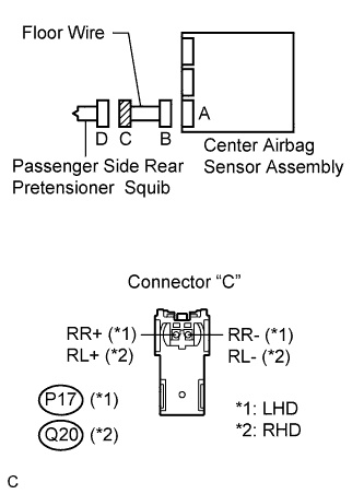
Check for a short to B+ in the circuit.
Connect the negative (-) terminal cable to the battery, and wait for at least 2 seconds.
Turn the engine switch on (IG).
Measure the voltage according to the value(s) in the table below.
- Standard voltage:
- LHD:
Tester connection
Condition
Specified condition
P17-1 (RR+) - Body ground
Engine switch on (IG)
Below 1 V
P17-2 (RR-) - Body ground
Engine switch on (IG)
Below 1 V
- RHD:
Tester connection
Condition
Specified condition
Q20-1 (RL+) - Body ground
Engine switch on (IG)
Below 1 V
Q20-2 (RL-) - Body ground
Engine switch on (IG)
Below 1 V
Check for an open in the circuit.
Turn the engine switch off.
Disconnect the negative (-) terminal cable from the battery, and wait for at least 90 seconds.
Measure the resistance according to the value(s) in the table below.
- Standard resistance:
- LHD:
Tester connection
Condition
Specified condition
P17-1 (RR+) - P17-2 (RR-)
Always
Below 1 Ω
- RHD:
Tester connection
Condition
Specified condition
Q20-1 (RL+) - Q20-2 (RL-)
Always
Below 1 Ω
Check for a short to ground in the circuit.
Measure the resistance according to the value(s) in the table below.
- Standard resistance:
- LHD:
Tester connection
Condition
Specified condition
P17-1 (RR+) - Body ground
Always
1 MΩ or higher
P17-2 (RR-) - Body ground
Always
1 MΩ or higher
- RHD:
Tester connection
Condition
Specified condition
Q20-1 (RL+) - Body ground
Always
1 MΩ or higher
Q20-2 (RL-) - Body ground
Always
1 MΩ or higher
Check for a short in the circuit.
Release the activation prevention mechanism built into connector "B" (Click here).
Measure the resistance according to the value(s) in the table below.
- Standard resistance:
- LHD:
Tester connection
Condition
Specified condition
P17-1 (RR+) - P17-2 (RR-)
Always
1 MΩ or higher
- RHD:
Tester connection
Condition
Specified condition
Q20-1 (RL+) - Q20-2 (RL-)
Always
1 MΩ or higher
|
|
||||
| OK | |
|
| 4. CHECK CENTER AIRBAG SENSOR ASSEMBLY |
Connect the connectors to the rear seat outer belt assembly (passenger side) and the center airbag sensor assembly.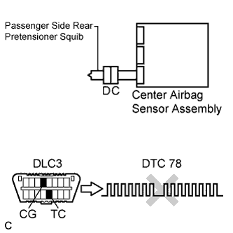
Connect the negative (-) terminal cable to the battery, and wait for at least 2 seconds.
Turn the engine switch on (IG), and wait for at least 60 seconds.
Clear the DTCs stored in the memory (Click here).
Turn the engine switch off.
Turn the engine switch on (IG), and wait for at least 60 seconds.
Check for DTCs (Click here).
- OK:
- DTC B1925, B1926, B1927, B1928 or 78 is not output.
- HINT:
- Codes other than DTC B1925, B1926, B1927, B1928 and 78 may be output at this time, but they are not related to this check.
|
|
||||
| OK | ||
 |
||
| ||