ON-VEHICLE INSPECTION
Inspection
| INSPECT CHECK VVT SENSOR OUTPUT VOLTAGE |

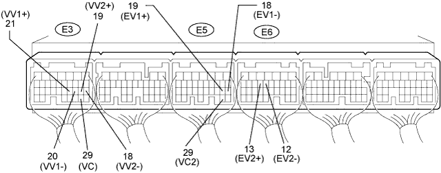

Turn the engine switch on (IG).
Check the voltage between the terminal.
- Standard voltage:
Tester Connection
Condition
Specified Condition
E3-29 (VC) - Body ground
Engine switch on (IG)
5 V
E3-29 (VC2) - Body ground
Engine switch on (IG)
5 V
While turning the crankshaft pulley by hand, measure the voltage between each terminal. Check that the voltage changes between the Hi range and Lo range shown in the table below.
- Standard voltage:
Sensor Position
Terminal No.
Voltage (Hi)
Voltage (Lo)
Bank 1 (Intake side)
VV1+ (E3-21) - VV1- (E3-20)
3.75 to 4.50 V
0.50 to 1.25 V
Bank 2 (Intake side)
VV2+ (E3-19) - VV2- (E3-18)
3.75 to 4.50 V
0.50 to 1.25 V
Bank 1 (Exhaust side)
EV1+ (E6-19) - EV1- (E36-18)
3.75 to 4.50 V
0.50 to 1.25 V
Bank 2 (Exhaust side)
EV2+ (E6-13) - EV2- (E6-12)
3.75 to 4.50 V
0.50 to 1.25 V