Footwell Light Circuit
Circuit diagnosis
DESCRIPTION
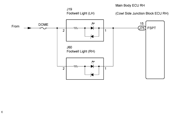
The main body ECU RH receives information regarding the door lock position switches, door courtesy switches, and engine switch, and turns on each footwell light.This illumination setting can be canceled using the light control rheostat.
WIRING DIAGRAM

INSPECTION PROCEDURE
| 1. PERFORM ACTIVE TEST BY INTELLIGENT TESTER |

Connect the intelligent tester to the DLC3.
Turn the engine switch on (IG).
Turn the intelligent tester main switch on.
Select the item(s) in the ACTIVE TEST, and check the operation.
ACTIVE TEST: MAIN BODY (Main body ECU RH) Item
Test Details
Diagnostic Note
Step Light Operation
Footwell lights ON / OFF
-
- OK:
- Footwell lights come on.
- HINT:
- The footwell lights RH and LH share the same power source. If either of the lights does not come on, there may be a problem in the part of the circuit that relates to that light. Therefore, inspect that part of the circuit.
|
|
||||

| OK | ||
 |
||
| ||
| 2. CHECK HARNESS AND CONNECTOR (MAIN BODY ECU RH - BATTERY) |
Disconnect the J75 main body ECU RH connector.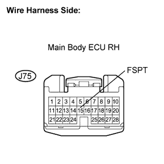
Measure the voltage according to the value(s) in the table.
- Standard voltage:
Tester Connection
Condition
Specified Condition
J75-15 (FSPT) - Body ground
Always
10 to 14 V
|
|
||||

| OK | ||
|
||
| ||