Interior Light Switch Signal Circuit
Circuit diagnosis
DESCRIPTION
The main body ECU RH receives information on the front interior light switch (marked ON/OFF).The main body ECU LH receives information on the front interior light switch (marked DOOR).
According to the position of each switch, the main body ECU RH controls the turning on and off of the interior lights, and the main body ECU LH controls the illuminated entry system.
WIRING DIAGRAM
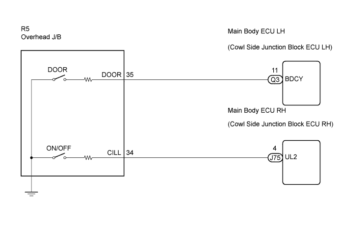

INSPECTION PROCEDURE
| 1. READ VALUE OF INTELLIGENT TESTER |

Connect the intelligent tester to the DLC3.
Turn the engine switch on (IG).
Turn the intelligent tester main switch on.
Select the item(s) in the DATA LIST, and read the display on the intelligent tester.
DATA LIST: Main Body (Main Body ECU RH) Item
Measurement Item / Display
(Range)
Normal Condition
Diagnostic Note
Illumination SW
Front interior light switch (marked ON/OFF) signal/ ON or OFF
ON: Front interior light switch (marked ON/OFF) is pushed in
OFF: Front interior light switch (marked ON/OFF) is not pushed in
-
DATA LIST: Body No. 3 (Main Body ECU LH) Item
Measurement Item / Display
(Range)
Normal Condition
Diagnostic Note
Interior Light
Front interior light switch (marked DOOR) signal/ ON or OFF
ON: Front interior light switch (marked DOOR) is pushed in
OFF: Front interior light switch (marked DOOR) is not pushed in
-
- OK:
- Switch condition can be displayed.
- Result:
Result
Proceed to
Indication for "ILLUMI SW" does not change
A
Indication for "INTERIOR LIGHT" does not change
B
Indications for both "ILLUMI SW" and "INTERIOR LIGHT" do not change
C
OK
D
|
|
||||
|
|
||||
|
|
||||

| D | ||
 |
||
| ||
| 2. INSPECT OVERHEAD J/B |
Remove the overhead J/B.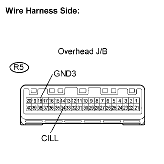
Measure the resistance according to the value(s) in the table.
- Standard resistance:
Tester Connection
Switch Condition
Specified Condition
R5-34 (CILL) - R5-18 (GND3)
Front interior light switch (marked ON/OFF) is not pushed in
10 kΩ or higher
R5-34 (CILL) - R5-18 (GND3)
Front interior light switch (marked ON/OFF) is pushed in
Approx. 10 Ω
|
|
||||

| OK | |
 |
| 3. CHECK HARNESS AND CONNECTOR (OVERHEAD J/B - MAIN BODY ECU RH) |
Disconnect the R5 overhead J/B connector.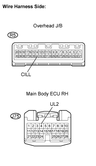
Disconnect the J75 main body ECU RH connector.
Measure the resistance according to the value(s) in the table.
- Standard resistance:
Tester Connection
Condition
Specified Condition
R5-34 (CILL) - J75-4 (UL2)
Always
Below 1 Ω
R5-34 (CILL) - Body ground
Always
10 kΩ or higher
|
|
||||
| OK | ||
|
||
| ||
| 4. INSPECT OVERHEAD J/B |
Remove the overhead J/B.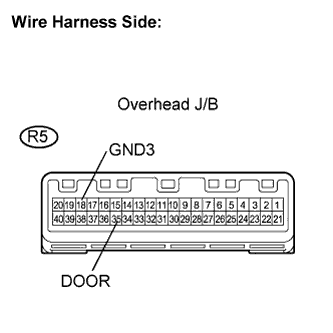
Measure the resistance according to the value(s) in the table.
- Standard resistance:
Tester Connection
Switch Condition
Specified Condition
R5-35 (DOOR) - R5-18 (GND3)
Front interior light switch (marked DOOR) is not pushed in
10 kΩ or higher
R5-35 (DOOR) - R5-18 (GND3)
Front interior light switch (marked DOOR) is pushed in
Approx. 10 Ω
|
|
||||
| OK | |
|
| 5. CHECK HARNESS AND CONNECTOR (OVERHEAD J/B - MAIN BODY ECU LH) |
Disconnect the R5 overhead J/B connector.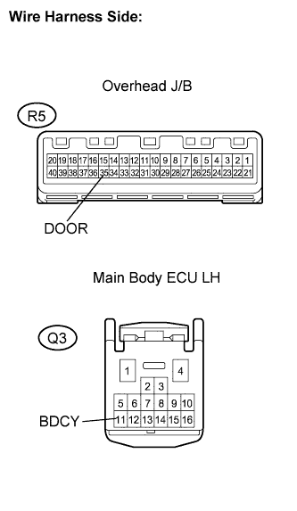
Disconnect the J75 main body ECU LH connector.
Measure the resistance according to the value(s) in the table.
- Standard resistance:
Tester Connection
Condition
Specified Condition
R5-35 (DOOR) - Q3-11 (BDCY)
Always
Below 1 Ω
R5-35 (DOOR) - Body ground
Always
10 kΩ or higher
|
|
||||
| OK | ||
|
||
| ||
| 6. INSPECT OVERHEAD J/B |
Remove the overhead J/B.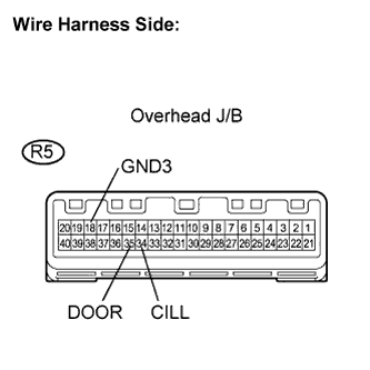
Measure the resistance according to the value(s) in the table.
- Standard resistance:
Tester Connection
Switch Condition
Specified Condition
R5-35 (DOOR) - R5-18 (GND3)
Front interior light switch (marked DOOR) is not pushed in
10 kΩ or higher
R5-35 (DOOR) - R5-18 (GND3)
Front interior light switch (marked DOOR) is pushed in
Approx. 10 Ω
R5-34 (CILL) - R5-18 (GND3)
Front interior light switch (marked ON/OFF) is not pushed in
10 kΩ or higher
R5-34 (CILL) - R5-18 (GND3)
Front interior light switch (marked ON/OFF) is pushed in
Approx. 10 Ω
|
|
||||
| OK | ||
|
||
| ||