TERMINALS OF ECU
System information
| CHECK MAIN BODY ECU RH |
Disconnect the RD and RK junction block connectors.
Disconnect the J75 ECU connector.
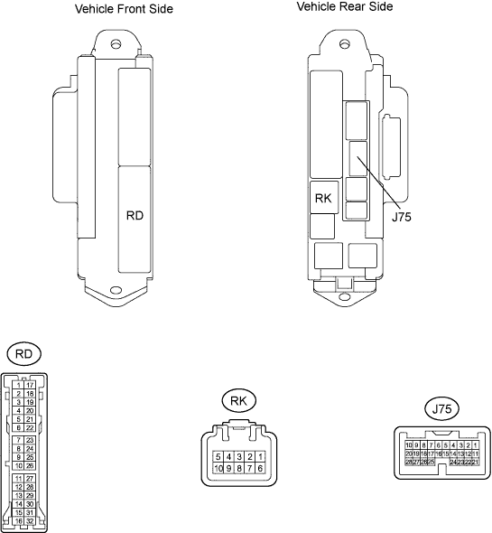

Measure the resistance and voltage according to the value(s) in the table below.
If the result is not as specified, there may be a malfunction on the wire harness side.Symbols (Terminal No.)
Wiring Color
Terminal Description
Condition
Specified Condition
BECU (RK-5 ) - Body ground
G-R - Body ground
Battery (power supply)
Always
10 to 14 V
GND1 (RD-17) - Body ground
W-B - Body ground
Ground
Always
Below 1 Ω
GND2 (RD-7) - Body ground
W-B - Body ground
Ground
Always
Below 1 Ω
Reconnect the RD and RK junction block connectors.
Reconnect the J75 ECU connector.
Measure the voltage according to the value(s) in the table below.
If the result is not as specified, the ECU may have a malfunction.Symbols (Terminal No.)
Wiring Color
Terminal Description
Condition
Specified Condition
TSW (J75-2) - Body ground
LG - Body ground
Luggage compartment door main opener switch signal input
Luggage compartment door main opener switch OFF
10 to 14 V
Luggage compartment door main opener switch ON
Below 1 V
TKUL (J75-3) - Body ground
P - Body ground
Luggage compartment door opener switch signal input
Luggage compartment door opener switch OFF
10 to 14 V
Luggage compartment door opener switch ON
Below 1 V