Reverse Shift-linked Function of Power Mirrors do not Operate
Circuit diagnosis
DESCRIPTION
A/T models:After the ECM receives a reverse signal from the park/neutral position switch, the ECM sends a reverse signal to the outer mirror control ECU via the CAN and BEAN communication systems. The outer mirror control ECU activates the mirror motor in response to the reverse signal.
M/T models:
After the main body ECU RH (cowl side J/B RH) receives a reverse signal from the back up light switch, the ECU sends a reverse signal to the outer mirror control ECU via the BEAN communication system. The outer mirror control ECU activates the mirror motor in response to the reverse signal.
WIRING DIAGRAM
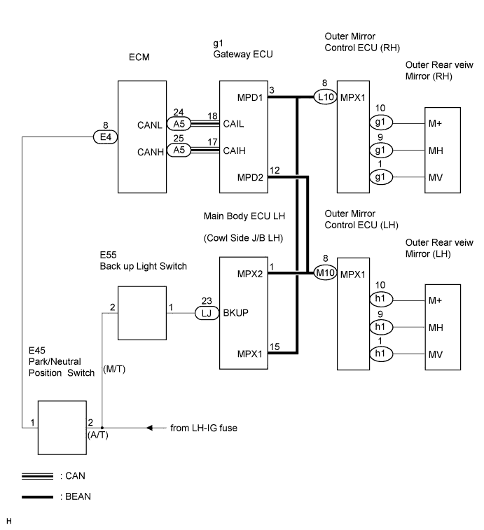

INSPECTION PROCEDURE
| 1. CHECK DTCs |

Select the DTC check on the intelligent tester to check for communication errors.
- Result:
Not output DTC codes
A
Output DTC codes (Multiplex communication)
B
Output DTC codes (CAN communication)
C
|
|
||||
|
|
||||

| A | |
 |
| 2. READ VALUE OF INTELLIGENT TESTER |
Check the DATA LIST for proper function of the reverse signal.
- P-J/B:
Item
Measurement item/Display (Range)
Normal Condition
Back-up Light Switch
Reverse signal/ON or OFF
ON: Shift is R position
OFF: Shift is except R position
|
|
||||

| NG | |
|
| 3. CHECK VEHICLE TYPE |
- Result:
M/T
A
A/T
B
|
|
||||
| A | |
|
| 4. CHECK WIRE HARNESS (BATTERY POSITIVE VOLTAGE) |
Disconnect the E55 connector.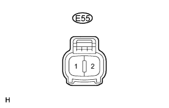
Measure the voltage according to the value(s) in the table below.
- Voltage:
Tester Connection
Condition
Specified Condition
E55-2 - Body ground
Engine switch on (IG)
10 to 14 V
|
|
||||
| OK | |
|
| 5. CHECK WIRE HARNESS (BACK UP LIGHT SWITCH ASSEMBLY - COWL SIDE J/B LH) |
Disconnect the E55 and LJ connectors.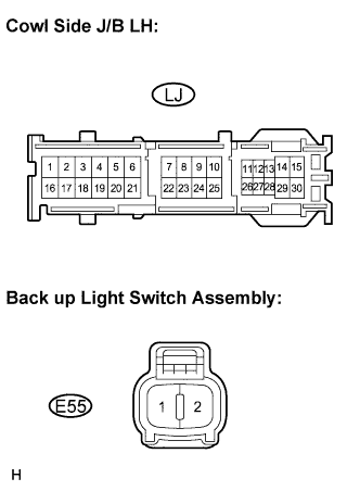
Measure the resistance according to the value(s) in the table below.
- Resistance:
Tester Connection
Condition
Specified Condition
E55-1 - LJ-23 (BKUP)
Always
Below 1 Ω
E55-1 - Body ground
Always
10 kΩ or higher
|
|
||||
| OK | |
|
| 6. INSPECT BACK UP LIGHT SWITCH ASSEMBLY |
Disconnect the E55 connector.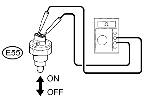
Measure the resistance according to the value(s) in the table below.
- Resistance:
Tester Connection
Condition
Specified Condition
E55-1 - E55-2
ON
Below 1 Ω
E55-1 - E55-2
OFF
10 kΩ or higher
|
|
||||
| OK | ||
 |
||
| ||
| 7. INSPECT OUTER REAR VIEW MIRROR ASSEMBLY |
Outer rear view mirror LH:Disconnect the h1 connector.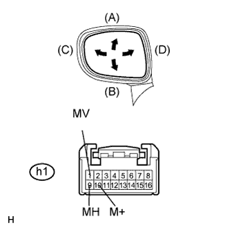
Apply battery voltage and check operation of the mirror face.
- Standard:
Measurement Condition
Mirror Operation
Battery positive (+) → h1-1 (MV)
Battery negative (-) → h1-10 (M+)
Turns upward (A)
Battery positive (+) → h1-10 (M+)
Battery negative (-) → h1-1 (MV)
Turns downward (B)
Battery positive (+) → h1-9 (MH)
Battery negative (-) → h1-10 (M+)
Turns left (C)
Battery positive (+) → h1-10 (M+)
Battery negative (-) → h1-9 (MH)
Turns right (D)
Outer rear view mirror RH:Disconnect the g1 connector.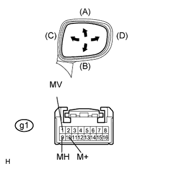
Apply battery voltage and check operation of the mirror face.
- Standard:
Measurement Condition
Mirror Operation
Battery positive (+) → g1-1 (MV)
Battery negative (-) → g1-10 (M+)
Turns upward (A)
Battery positive (+) → g1-10 (M+)
Battery negative (-) → g1-1 (MV)
Turns downward (B)
Battery positive (+) → g1-9 (MH)
Battery negative (-) → g1-10 (M+)
Turns left (C)
Battery positive (+) → g1-10 (M+)
Battery negative (-) → g1-9 (MH)
Turns right (D)
|
|
||||
| OK | ||
|
||
| ||
| 8. CHECK WIRE HARNESS (BATTERY POSITIVE VOLTAGE) |
Disconnect the E45 connector.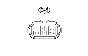
Measure the voltage according to the value(s) in the table below.
- Voltage:
Tester Connection
Condition
Specified Condition
E45-2 - Body ground
Engine switch on (IG)
10 to 14 V
|
|
||||
| OK | |
|
| 9. CHECK WIRE HARNESS (PARK/NEUTRAL POSITION SWITCH - ECM) |
Disconnect the E45 and E4 connectors.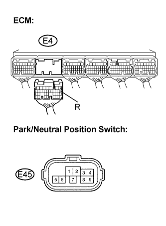
Measure the resistance according to the value(s) in the table below.
- Resistance:
Tester Connection
Condition
Specified Condition
E45-1 - E4-8
Always
Below 1 Ω
E45-1 - Body ground
Always
10 kΩ or higher
|
|
||||
| OK | |
|
| 10. INSPECT PARK/NEUTRAL POSITION SWITCH ASSEMBLY |
Disconnect the E45 connector.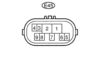
Measure the resistance according to the value(s) in the table below.
- Resistance:
Shift Position
Tester Connection
Specified Condition
P
E45-1 - E45-2
Below 1 Ω
Except P
E45-1 - E45-2
10 kΩ or higher
|
|
||||
| OK | |
|
| 11. REPLACE GATEWAY ECU |
Replace the gateway ECU.
| NEXT | |
|
| 12. CONFIRM MIRROR OPERATION |
|
|
||||
| OK | ||
|
||
| ||