Power Mirrors do not Return to Memorized Position
Circuit diagnosis
DESCRIPTION
When the seat memory switch M1, M2 or M3 is pressed, the position control ECU & switch (Seat ECU) transmits a signal of the memorized mirror position to the outer mirror control ECU by way of the power window regulator master switch. Then, the outer mirror control ECU drives the mirror motor.- HINT:
- The power mirror control system is a part of the multiplex communication system. This system features shared communication wiring that reduces the wiring complexity of the communication lines. The first step in any repair is to confirm the proper operation of the communication system. Proceed with troubleshooting after the communication has been verified (See the Multiplex Communication System).
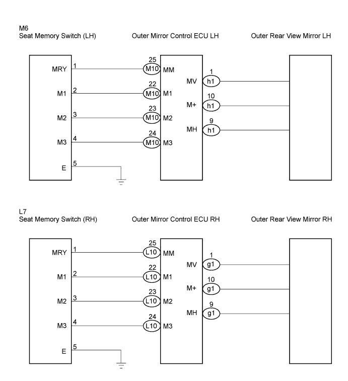
WIRING DIAGRAM
INSPECTION PROCEDURE

| 1. READ VALUE OF INTELLIGENT TESTER |

Check the DATA LIST for proper function of the seat memory switch.
- D-Seat:
Item
Switch Position
Specified condition
Memory No1
Driving position memorized in seat memory switch M 1/NOT MEM or MEM
MEM: Memorized
NOT MEM: Not memorized
Memory No2
Driving position memorized in seat memory switch M 2/NOT MEM or MEM
Memory No3
Driving position memorized in seat memory switch M 3/NOT MEM or MEM
|
|
||||

| NG | |
 |
| 2. CHECK SEAT MEMORY SWITCH |
Remove the seat memory switch.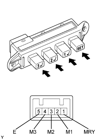
Measure the resistance according to the value(s) in the table below when the switch is operated.
- Resistance:
Tester Connection
Switch Condition
Specified Condition
1 - 5
"SET" switch ON
Below 1 Ω
1 - 5
"SET" switch OFF
10 kΩ or higher
2 - 5
"1" switch ON
Below 1 Ω
2 - 5
"SET" switch OFF
10 kΩ or higher
3 - 5
"2" switch ON
Below 1 Ω
3 - 5
"SET" switch OFF
10 kΩ or higher
4 - 5
"3" switch ON
Below 1 Ω
4 - 5
"SET" switch OFF
10 kΩ or higher
|
|
||||
| OK | |
|
| 3. CHECK WIRE HARNESS (SEAT MEMORY SWITCH - OUTER MIRROR CONTROL ECU) |
Disconnect the M6 (L7) and M10 (L10) switch connectors.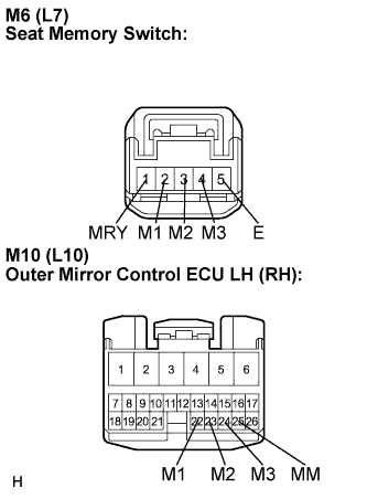
Measure the resistance according to the value(s) in the table below.( ): RH side
- Resistance:
- LH side:
Tester Connection
Condition
Specified Condition
M6-1 (MRY) - M10-25 (MM)
Always
Below 1 Ω
M6-2 (M1) - M10-22 (M1)
Always
Below 1 Ω
M6-3 (M2) - M10-23 (M2)
Always
Below 1 Ω
M6-4 (M3) - M10-24 (M3)
Always
Below 1 Ω
M6-5 (E) - Body ground
Always
Below 1 Ω
- RH side:
Tester Connection
Condition
Specified Condition
L7-1 (MRY) - L10-25 (MM)
Always
Below 1 Ω
L7-2 (M1) - L10-22 (M1)
Always
Below 1 Ω
L7-3 (M2) - L10-23 (M2)
Always
Below 1 Ω
L7-4 (M3) - L10-24 (M3)
Always
Below 1 Ω
L7-5 (E) - Body ground
Always
Below 1 Ω
|
|
||||
| OK | |
|
| 4. INSPECT OUTER REAR VIEW MIRROR ASSEMBLY |
Outer rear view mirror LH:Disconnect the h1 connector.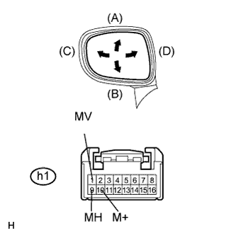
Apply battery voltage and check operation of the mirror face.
- Standard:
Measurement Condition
Mirror Operation
Battery positive (+) → h1-1 (MV)
Battery negative (-) → h1-10 (M+)
Turns upward (A)
Battery positive (+) → h1-10 (M+)
Battery negative (-) → h1-1 (MV)
Turns downward (B)
Battery positive (+) → h1-9 (MH)
Battery negative (-) → h1-10 (M+)
Turns left (C)
Battery positive (+) → h1-10 (M+)
Battery negative (-) → h1-9 (MH)
Turns right (D)
Outer rear view mirror RH:Disconnect the g1 connector.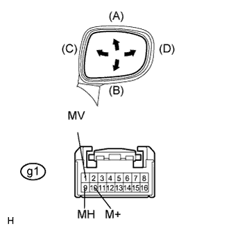
Apply battery voltage and check operation of the mirror face.
- Standard:
Measurement Condition
Mirror Operation
Battery positive (+) → g1-1 (MV)
Battery negative (-) → g1-10 (M+)
Turns upward (A)
Battery positive (+) → g1-10 (M+)
Battery negative (-) → g1-1 (MV)
Turns downward (B)
Battery positive (+) → g1-9 (MH)
Battery negative (-) → g1-10 (M+)
Turns left (C)
Battery positive (+) → g1-10 (M+)
Battery negative (-) → g1-9 (MH)
Turns right (D)
|
|
||||
| OK | ||
 |
||
| ||