B2288
Diagnostic trouble codes
DESCRIPTION
This DTC is output when the power source control ECU cannot detect the unlock condition of the steering lock within a specified time.- HINT:
- When the power source control ECU is replaced with a new one and the negative (-) battery terminal is connected, the power source mode becomes the IG-ON mode. When the battery is removed and reinstalled, the power source mode that was selected when the battery was removed is restored.
| DTC No. |
DTC Detection Condition |
Trouble Area |
| B2288 |
After turning engine switch from off to on (IG), the steering wheel does not unlock for a certain period of time (ECU unlocks steering wheel only when it receives an unlock signal from LIN communication and cable) |
|
WIRING DIAGRAM
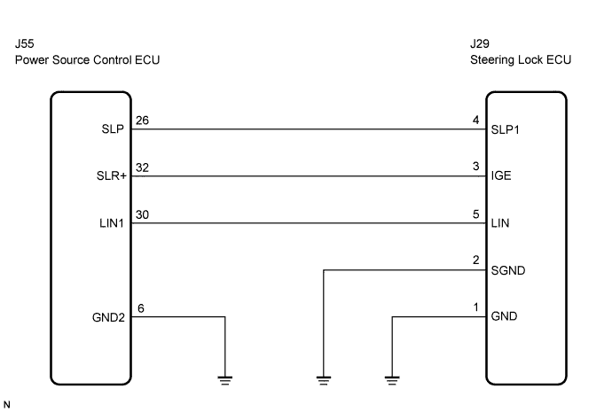

INSPECTION PROCEDURE
| 1. CHECK FOR DTCS |

Delete the DTC (Click here).
Check for DTCs again.
- OK:
- DTC B2785, DTC B2287 and DTC B2781 are not output.
- HINT:
- If DTC B2785 is output (Click here).
- If DTC B2287 is output (Click here).
- If DTC B2278 is output (Click here).
- If DTC B2785 is output (Click here).
|
|
||||

| OK | |
 |
| 2. CHECK CONNECTORS |
Check that the connectors are securely connected and the terminals are not deformed or loose.
- OK:
- The connectors are securely connected and the terminals are not deformed or loose.
|
|
||||
| OK | |
|
| 3. CHECK WIRE HARNESS (POWER SOURCE CONTROL ECU - BODY GROUND) |
Disconnect the J55 ECU connector.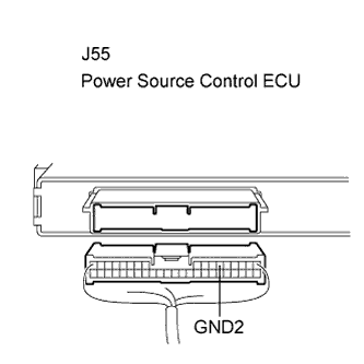
Measure the resistance according to the value(s) in the table below.
- Standard resistance:
Tester Connection (Symbols)
Condition
Specified Condition
J55-6 (GND2) - Body ground
Always
Below 1 Ω
|
|
||||
| OK | |
|
| 4. CHECK WIRE HARNESS (POWER SOURCE CONTROL ECU - STEERING LOCK ECU) |
Disconnect the J29 ECU connector.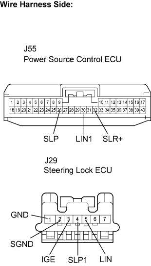
Measure the resistance according to the value(s) in the table below.
- Standard resistance:
Tester Connection
Condition
Specified Condition
J55-26 (SLP) - J29-4 (SLP1)
Always
Below 1 Ω
J55-32 (SLR+) - J29-3 (IGE)
Always
Below 1 Ω
J55-30 (LIN1) - J29-5 (LIN)
Always
Below 1 Ω
J29-2 (SGND) - Body ground
Always
Below 1 Ω
J29-1 (GND) - Body ground
Always
Below 1 Ω
J55-26 (SLP) or J29-4 (SLP1) - Body ground
Always
10 kΩ or higher
J55-32 (SLR+) or J29-3 (IGE) - Body ground
Always
10 kΩ or higher
J55-30 (LIN1) or J29-5 (LIN) - Body ground
Always
10 kΩ or higher
|
|
||||
| OK | |
|
| 5. INSPECT POWER SOURCE CONTROL ECU |
Reconnect the J55 ECU connector.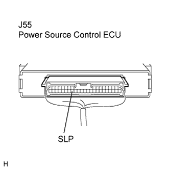
Connect the oscilloscope to the power source control ECU terminals specified in the table below and check the waveform.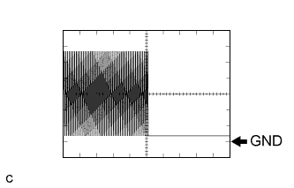
Item
Contents
Terminal (Symbols)
J55-26 (SLP) - Body ground
Equipment Setting
2 V/DIV, 100 ms/DIV
Condition
Engine switch on (IG)
- OK:
- The waveform appears as shown in the illustration.
- HINT:
- The waveform varies depending on the contents of communication.
|
|
||||
| OK | |
|
| 6. INSPECT STEERING LOCK ECU |
Reconnect the J29 ECU connector.
Connect the oscilloscope to the power source control ECU terminals specified in the table below and check the waveform.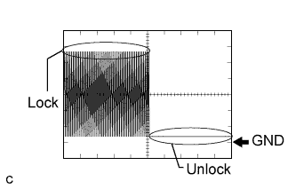
Item
Contents
Terminal (Symbols)
J55-26 (SLP) - Body ground
Equipment Setting
2 V/DIV, 100 ms/DIV
Condition
Steering is LOCK / UNLOCK
- OK:
- The waveform appears as shown in the illustration.
- HINT:
- The waveform varies depending on the contents of communication.
|
|
||||
| OK | |
|
| 7. RECHECK FOR DTC |
Delete the DTCs (Click here).
Check for DTCs again.
- OK:
- DTC B2288 is not output.
|
|
||||
| OK | ||
 |
||
| ||