Display Signal Circuit between Television Camera ECU and Multi-display
Circuit diagnosis
DESCRIPTION
This is the display signal circuit from the television camera ECU to the multi-display.WIRING DIAGRAM
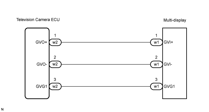

INSPECTION PROCEDURE
| 1. CHECK HARNESS AND CONNECTOR (MULTI-DISPLAY - TELEVISION CAMERA ECU) |

Disconnect the multi-display connector w1 and television camera ECU connector w2.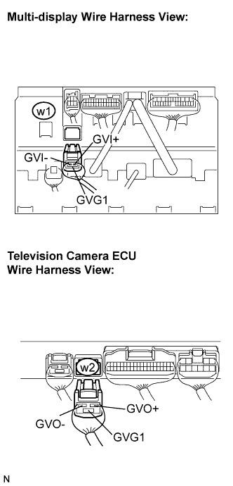
Measure the resistance according to the value(s) in the table below.
- Standard resistance:
Tester connection
Condition
Specified condition
GVI+ - GVO+
Always
Below 1 Ω
GVI- - GVO-
Always
Below 1 Ω
GVG1 - GVG1
Always
Below 1 Ω
GVI- - Body ground
Always
10 kΩ or higher
GVI+ - Body ground
Always
10 kΩ or higher
|
|
||||

| OK | ||
 |
||
| ||