Clearance Sonar Main Switch Circuit
Circuit diagnosis
DESCRIPTION
The clearance sonar main switch is installed on the instrument panel safety pad assembly.When the clearance sonar main switch in turned ON, an ON signal is sent to the clearance warning ECU through the BEAN line. The clearance sonar system operates according to this signal.
WIRING DIAGRAM
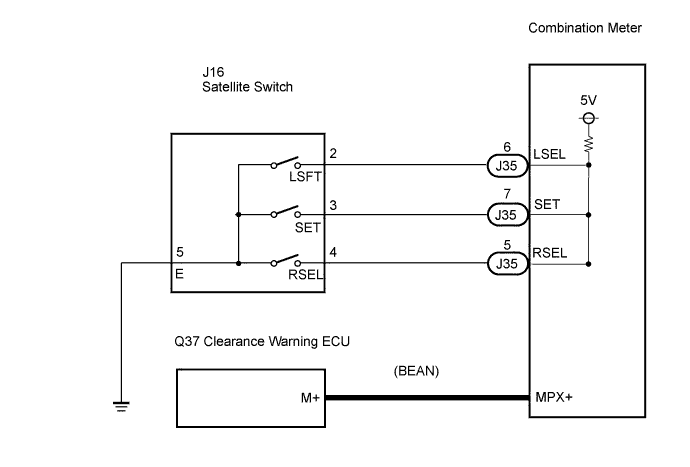

INSPECTION PROCEDURE
| 1. CHECK MULTIPLEX COMMUNICATION SYSTEM |

If the multiplex communication system is operating normally, proceed to the next step.
| NEXT | |
 |
| 2. READ VALUE OF INTELLIGENT TESTER |
Connect the intelligent tester to the DLC3.
Turn the engine switch ON (IG).
Turn the intelligent tester main switch ON.
Turn the clearance sonar main switch ON.
Select the item below in the Data List, and read its value displayed on the intelligent tester to check the clearance sonar main switch.
- Result:
Clearance warning ECU: Item
Measurement / Range (Display)
Normal Condition
Diagnostic Note
MAIN SW
Clearance sonar main switch / OFF or ON
OFF: Clearance sonar main switch OFF
ON: Clearance sonar main switch ON
-
|
|
||||

| NG | |
|
| 3. PERFORM SATELLITE SWITCH |
Check operation speed and tach indicator system (Click here).
- Result:
Result
Proceed to
The system operates normally
OK
The system does not operate normally
NG
|
|
||||
| OK | |
|
| 4. REPLACE CLEARANCE WARNING ECU ASSEMBLY |
Replace the clearance warning ECU (Click here).
| NEXT | |
|
| 5. CHECK OPERATION CLEARANCE SONAR SYSTEM |
Check the operation of the clearance sonar system (Click here).
- Result:
Result
Proceed to
The system operates normally
OK
The system does not operate normally
NG
|
|
||||
| OK | ||
 |
||
| ||