No. 1 Clearance Warning Buzzer Circuit
Circuit diagnosis
WIRING DIAGRAM
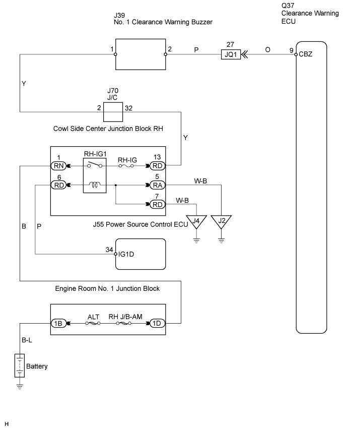

INSPECTION PROCEDURE
| 1. PERFORM ACTIVE TEST BY INTELLIGENT TESTER |

Connect the intelligent tester to the DLC3.
Turn the engine switch ON (IG).
Turn the intelligent tester main switch ON.
Turn the clearance sonar main switch ON.
Select the Active Test, use the intelligent tester to generate a control command, and then check that the buzzer operates.
Clearance warning ECU: Item
Vehicle Condition / Test Details
Diagnostic Note
REAR BUZZER
Rear buzzer (Clearance warning buzzer) / STOP or OPERATE
-
- OK:
- No. 1 clearance warning buzzer sounds.
|
|
||||

| NG | |
 |
| 2. CHECK WIRE HARNESS (NO. 1 CLEARANCE WARNING BUZZER - CLEARANCE WARNING ECU) |
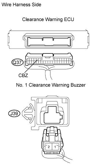 |
Disconnect the Q37 ECU connector.
Disconnect the J39 buzzer connector.
Measure the resistance of the wire harness side connectors.
- Standard resistance:
Tester Connection
Condition
Specified Condition
CBZ (Q37-9) - J39-2
Always
Below 1 Ω
CBZ (Q37-9) - Body ground
Always
10 kΩ or higher
|
|
||||
| OK | |
|
| 3. CHECK NO. 1 CLEARANCE WARNING BUZZER (TERMINAL VOLTAGE) |
Disconnect the J39 buzzer connector.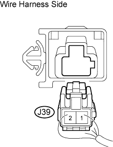
Measure the voltage of the connector.
- Standard voltage:
Tester Connection
Condition
Specified Condition
J39-1 - Body ground
Engine switch ON (IG)
10 to 14 V
|
|
||||
| OK | |
|
| 4. INSPECT NO. 1 CLEARANCE WARNING BUZZER |
Apply battery voltage and check operation of the warning buzzer, as shown in the table.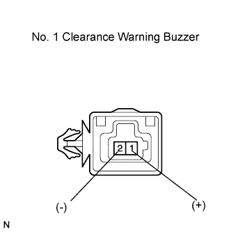
Measurement Condition
Specified Condition
Battery positive (+) → J39-1
Battery negative (-) → J39-2
Operating sound occurs
- HINT:
- The clearance warning buzzer does not sound without battery voltage applied because the buzzer is a separately-excited type.
|
|
||||
| OK | ||
 |
||
| ||