- MPEG1 LAYER3: 32, 44.1, 48 (kHz)
- MPEG2 LSF LAYER3: 16, 22.05, 24 (kHz)
| Last Modified: 11-27-2007 | 1.6 D | |
| Service Category: Audio/Visual/Telematics | Section: Navigation/Multi Info Display | |
| Model Year: 2008 | Model: LX570 | Doc ID: RM000000NY600WX |
| Title: NAVIGATION / MULTI INFO DISPLAY: NAVIGATION SYSTEM: SYSTEM DESCRIPTION (2008 LX570) | ||
SYSTEM DESCRIPTION
1. NAVIGATION SYSTEM OUTLINE
(a) Vehicle position tracking methods
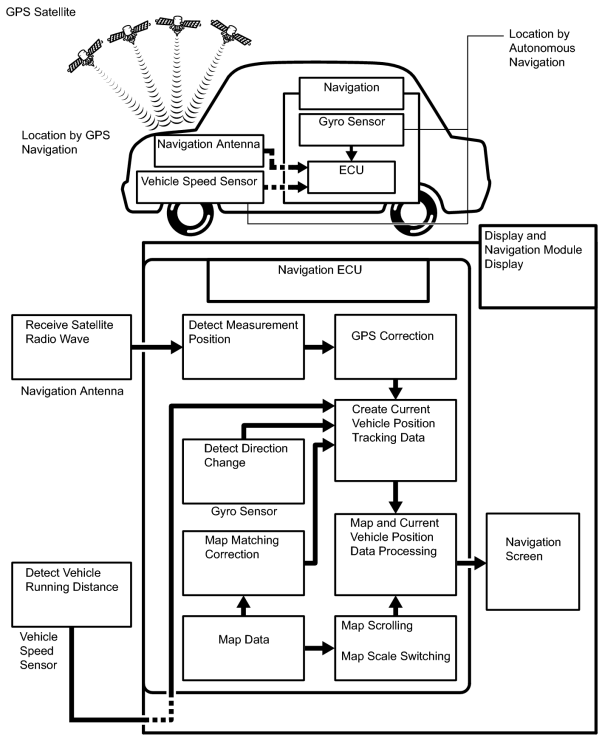
(1) It is essential that the navigation system correctly tracks the current vehicle position and displays it on the map. There are 2 methods to track the current vehicle position: autonomous (dead reckoning) and GPS* (satellite) navigation. Both navigation methods are used in conjunction with each other.
HINT:
*: GPS (Global Positioning System)
|
Operation |
Description |
|---|---|
|
Vehicle Position Calculation |
The display and navigation module display calculates the current vehicle position (direction and current position) using the direction deviation signal from the gyro sensor and running distance signal from the vehicle speed sensor, and creates the driving route. |
|
Map Display Processing |
The display and navigation module display processes the vehicle position data, vehicle running track, and map data from the map disc. |
|
Map Matching |
The map data from the map disc is compared to the vehicle position and running track data. Then, the vehicle position is matched with the nearest road. |
|
GPS Correction |
The vehicle position is matched to the position measured by the GPS. Then, the measurement position data from the GPS unit is compared with the vehicle position and running track data. If the position is very different, the GPS measurement position is used. |
|
Distance Correction |
The running distance signal from the vehicle speed sensor includes error caused by tire wear and slippage between the tires and road surface. Distance correction is performed to account for this. The display and navigation module display automatically offsets the running distance signal to make up for the difference between it and the distance data of map. The offset is automatically updated. |
HINT:
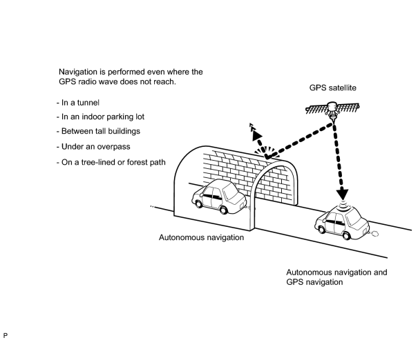
The combination of autonomous and GPS navigation makes it possible to display the vehicle position even when the vehicle is in places where the GPS radio wave cannot be received. When only autonomous navigation is used, the mapping accuracy may slightly decline.
(b) Autonomous navigation
This method determines the relative vehicle position based on the running track determined by the gyro and vehicle speed sensors located in the display and navigation module display.
(1) Gyro sensor
Calculates the direction by detecting angular velocity. It is located in the display and navigation module display.
(2) Vehicle speed sensor
Used to calculate the vehicle running distance.
(c) GPS navigation (satellite navigation)
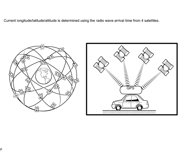
This method detects the absolute vehicle position using radio waves from a GPS satellite*.
HINT:
*: GPS satellites were launched by the U.S. Department of Defense for military purposes.
|
Number of Satellites |
Measurement |
Description |
|---|---|---|
|
2 or less |
Measurement is impossible |
The vehicle position cannot be obtained because the number of satellites is not enough. |
|
3 |
2-dimensional measurement is possible |
The vehicle position is obtained based on current longitude and latitude (this is less precise than 3-dimensional measurement). |
|
4 |
3-dimensional measurement is possible |
The vehicle position is obtained based on current longitude, latitude and altitude. |
(d) Map matching
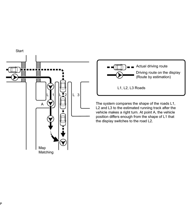
The current driving route is calculated by autonomous navigation (according to the gyro sensor and vehicle speed sensor) and GPS navigation. This information is then compared with possible road shapes from the map data in the map disc and the vehicle position is set onto the most appropriate road.
2. TOUCH SCREEN OUTLINE
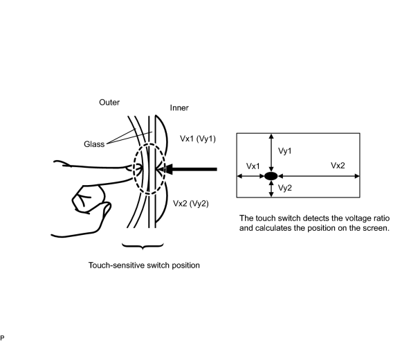
(a) Touch switch
Touch switches are touch-sensitive (interactive) switches operated by touching the screen. When a switch is pressed, the outer glass bends to contact the inner glass at the pressed position. By doing this, the voltage ratio is measured and the pressed position is detected.
3. NOTICE FOR HARD DISC DRIVE
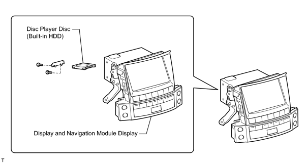
(a) The disc player disc has a built-in hard disc drive (HDD) for storing maps and other data used by the navigation system. When handling the disc player disc, follow the precautions below.
|
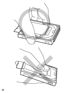
(1) Do not touch the cover of the HDD. NOTICE:
When removing or installing the disc player disc, hold it as shown in the illustration. |
(2) Avoid vibrations and impacts.
NOTICE:
- Do not drop or strike the disc player disc. Do not use a disc player disc that has been dropped or struck.
- Prepare a new disc player disc before removing the disc player disc.
(3) Avoid condensation.
- Introducing the disc player disc to sudden temperature changes may cause condensation to form inside it, and may lead to malfunctions in the HDD.
- The removed display and navigation module display must be stored in an environment where the temperature, humidity, etc., is the same as the vehicle interior, and the disc player disc must not be removed.
- If transporting the disc player disc from its storage area to a location where the temperature, humidity, etc., is different, allow some time for it to adapt to the surrounding environment.
(4) Avoid static electricity.
- Touching the connector terminals may transmit static electricity to the inner circuits and may lead to malfunctions in the HDD.
- When installing or removing the disc player disc, use the recommended tools and observe all precautions to prevent damage to the system by electrostatic discharge (ESD).
(5) Keep away from magnetic items.
NOTICE:
Keep speakers, motors, magnetized tools, etc., away from the disc player disc.
(b) Replace the disc player disc.
(1) After removing and installing the disc player disc, use the HDD information screen to perform the SMART inspection and confirm that there are no malfunctions in the HDD
 .
.
4. DISC PLAYER OUTLINE
(a) A disc player uses a laser pickup to read digital signals recorded on discs. By converting the digital signals to analog, music and other content can be played.
CAUTION:
Do not look directly at the laser pickup because the disc player uses an invisible laser beam. Be sure to operate the player only as instructed.
NOTICE:
- Do not disassemble any part of the disc player.
- Do not apply oil to the disc player.
- Do not insert anything but a disc into the disc player.
(b) Usable discs
(1) Disc player
This player can only play audio CDs, CD-Rs (CD-Recordable), CD-RWs (CD-Re Writable), DVD videos, DVD audio, and video CDs that have any of the following marks:

(c) Precautions for handing disc
NOTICE:
- Copy-controlled CDs cannot be used.
- Some CD-Rs and CD-RWs are not playable as a result of: 1) the type of recording method used, 2) the type of disc, 3) scratches, 4) contamination, or 5) the disc being in the vehicle for an extended amount of time, leading to deterioration.
- CD-Rs and CD-RWs that have not been finalized cannot be played.
- PAL or SECAM color television standard discs cannot be played (only NTSC discs can be played).
- DualDiscs that mate DVD recorded material on one side with CD digital audio material on the other cannot be played.
- When handling a disc, be careful not to put fingerprints, stains or scratches on the disc.
- When holding a disc, pinch the center hole and edge of the disc with your fingers. Face the printed side upward.
- If a disc is ejected by pressing the eject button and left partially ejected for an extended period of time, the disc may become deformed and unusable.
- A disc may not be able to be ejected or the player may become damaged if: 1) cellophane tape, stickers, CD-R labels or rental CD labels are attached; or 2) residue from removed tape, stickers or labels remains.
- Avoid direct sunlight when storing discs as they may become deformed and unusable.
- Do not use uniquely-shaped discs as they may damage the player.
- Do not use discs where part of the recording surface is transparent or translucent. if used, the disc may become unable to be inserted, ejected and played.
HINT:
- Just as condensation fogs the vehicle windows during wet or cold weather, condensation may also form inside the player. If condensation forms, disc skipping or playback stoppage may occur. Ventilate or dehumidify the vehicle for a while before using the player.
- If the player vibrates severely due to driving on a rough road, the disc may skip.
(d) Cleaning
NOTICE:
Do not use lens cleaner when cleaning the player, as it may damage the pickup part of the player.
|
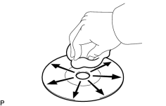
(1) To clean dirty discs, use a dry, soft cloth such as those used for glasses with plastic lenses. Lightly wipe radially from the center of the disc. NOTICE:
|
5. MP3/WMA OUTLINE
HINT:
Some audio and visual systems do not support the WMA format.
(a) Playable MP3 file standards
|
Compatible standard |
MP3 (MPEG1 LAYER3, MPEG2 LSF LAYER3) |
|
Compatible sampling frequency |
|
|
Compatible bit rate |
|
|
Compatible channel mode |
Stereo, joint stereo, dual channel, monaural |
(b) Playable WMA file standards
|
Compatible standard |
WMA Ver. 7, 8, and 9 |
|
Compatible sampling frequency |
32, 44.1, 48 (kHz) |
|
Compatible bit rate |
|
(c) ID3 tag and WMA tag
(1) Additional textual information called ID3 tags can be input to MP3 files. Information such as song titles and artist names can be stored.
HINT:
This player is compatible with the ID3 tags of ID3 Ver. 1.0 and 1.1, and ID3 Ver. 2.2 and 2.3. (Number of characters complies with ID3 Ver. 1.0 and 1.1.)
(2) Additional textual information called WMA tags can be input to WMA files. Information such as song titles and artist names can be stored.
(d) Usable media
(1) Only CD-ROMs, CD-Rs (CD-Recordable), and CD-RWs (CD-ReWritable) can be used to play MP3/WMA files.
NOTICE:
- CD-Rs and CD-RWs are more easily affected by a hot and humid environment than discs used for normal audio CDs. For this reason, some CD-Rs and CD-RWs may not be playable.
- If there are fingerprints or scratches on the disc, the disc may not be playable or the CD may skip.
- Some CD-Rs and CD-RWs deteriorate if they are left in the cabin for a long time.
- Keep CD-Rs and CD-RWs in a storage case that is non-transparent.
(e) Usable media format
(1) Usable media format
|
Disc format |
CD-ROM Mode 1, CD-ROM XA Mode 2 Form 1 |
|
File format |
ISO09660 Level 1 and Level 2 (Joliet, Romeo) |
HINT:
- As for MP3/WMA files written in any format other than those above, the contents of the files may not be playable or the file names or folder names may not be displayed correctly.
- This player is compatible with multi-session discs and can play CD-Rs and CD-RWs on which MP3/WMA files are added. However, only the first session can be played.
- Discs whose first session includes both music data and MP3 or WMA format data cannot be played.
(2) Standards and restrictions
|
Maximum directory levels |
8 levels |
|
Maximum number of characters for a folder name/file name |
32 characters |
|
Maximum number of folders |
192 (Including empty folders, root folders, and folders that do not contain MP3/WMA files) |
|
Maximum number of files in a disc |
255 (Including non-MP3/WMA files) |
(f) File names
(1) Only files with an extension of ".mp3" or ".wma" can be recognized and played as MP3 or WMA files.
(2) Save MP3 or WMA files with an extension of ".mp3" or ".wma".
NOTICE:
If saving non-MP3 or non-WMA files with an extension of ".mp3" or ".wma", those files are wrongly recognized as MP3 or WMA files and played. A loud noise may occur and damage to the speaker may result.
6. "BLUETOOTH" OUTLINE
(a) "Bluetooth" is a trademark owned by Bluetooth SIG, Inc.
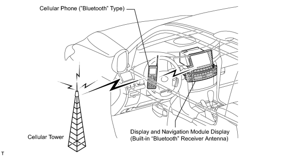
(b) "Bluetooth" is a new wireless connection technology that uses the 2.4 GHz frequency band. This makes it possible to connect a cellular phone ("Bluetooth" capable phone*) to the display and navigation module display ("Bluetooth" system is built-in) through the handsfree function of the cellular phone, even if it is in a pocket or bag. As a result, it is not necessary to directly connect the display and navigation module display to the cellular phone.
HINT:
*: The communication performance of "Bluetooth" may vary depending on the "Bluetooth" version, obstructions or radio wave conditions between communication devices, electromagnetic radiation, communication device sensitivity, or antenna capacity.
7. AVC-LAN DESCRIPTION
(a) What is AVC-LAN?
AVC-LAN, an abbreviation for "Audio Visual Communication Local Area Network", is a united standard developed by manufacturers in affiliation with Toyota Motor Corporation. This standard pertains to audio and visual signals as well as switch and communication signals.
(b) Purpose:
Recently, car audio systems have rapidly developed and the functions have vastly changed. The conventional car audio system is being integrated with multimedia interfaces similar to those in navigation systems. At the same time, customers are demanding higher quality from their audio systems. This is merely an overview of the standardization background. The specific purposes are as follows:
(1) To solve sound problems, etc. caused by using components of different manufacturers through signal standardization.
(2) To allow each manufacturer to concentrate on developing products they do best. From this, reasonably priced products can be produced.
HINT:
- If a short +B or short to ground is detected in the AVC-LAN circuit, communication is interrupted and the navigation system will stop functioning.
- The display and navigation module display is the master unit.
8. RBDS FUNCTION OUTLINE (BROADCAST IN NORTH AMERICA ONLY)
The Radio Broadcast Data System (RBDS) is broadcast through conventional FM radio broadcasts. Even if a vehicle changes locations, the same information can be received from several FM stations without breaks. Information such as song names, traffic information, broadcast station names, etc. can be received.
9. SDARS SYSTEM FUNCTION OUTLINE (BROADCAST IN NORTH AMERICA ONLY)
Satellite Digital Audio Radio Service (SDARS) is a satellite digital radio broadcast provided by XM Satellite Radio Inc. The broadcast (pay-type) is performed through satellites and terrestrial repeater networks. Several unique channels are available, and even if a vehicle changes locations, the same information can be received without breaks. Information such as song names, broadcast station names, etc. can be received. Also, traffic information can be received and displayed on the navigation screen.
NOTICE:
To receive an audio-visual pay-type broadcasts, the customer must enter into a pay-type contract with XM Satellite Radio Inc. After entering into a contract, an ID registration is required. Also, if parts are replaced, the ID must be reregistered. Refer to the owner's manual for information on how to register the ID.
10. COMMUNICATION SYSTEM OUTLINE
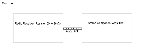
(a) Components of the navigation system communicate with each other via the AVC-LAN and AVC-LAN plus.
(b) The radio receiver assembly has enough resistance (60 to 80 Ω) necessary for transmitting communication signals. This is essential for communication.
(c) If a short circuit or open circuit occurs in the AVC-LAN circuit, communication is interrupted and the navigation system will stop functioning.
11. DIAGNOSTIC FUNCTION OUTLINE
(a) The navigation system has a diagnostic function (the result is indicated on the master unit).
(b) A 3-digit hexadecimal component code (physical address) is allocated to each component on the AVC-LAN and AVC-LAN plus. Using this code, the component in the diagnostic function can be displayed.
12. DIAGNOSIS DISPLAY DETAILED DESCRIPTION
HINT:
- This section contains a detailed description of displays within diagnostic mode.
- Illustrations may differ from the actual vehicle depending on the device settings and options. Therefore, some detailed areas may not be exactly the same as on the actual vehicle.
(a) SYSTEM CHECK
(1) System Check Mode Screen
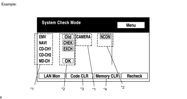
*1: Device Names and Hardware Address
HINT:
- Registered device names are displayed.
-
If a device name is unknown to the system, its physical address is shown instead.
Address No.
Name
Address No.
Name
110
EMV
120
AVX
128
1DIN TV
140
AVN
144
G-BOOK
178
NAVI
17C
MONET
190
AUDIO H/U
1AC
CAMERA-C
1B0
Rr-TV
1C0
Rr-CONT
19D
BT-HF
1C4
PANEL
1C6
G/W
1C8
FM-M-LCD
1D8
CONT-SW
1EC
Body
118
EMVN
1F1
XM
1F2
SIRIUS
230
TV-TUNER
240
CD-CH2
250
DVD-CH
280
CAMERA
360
CD-CH1
3A0
MD-CH
17D
TEL
440
DSP-AMP
530
ETC
1F6
RSE
1A0
DVD-P
1D6
CLOCK
238
DTV
480
AMP
*2: Check Result
HINT:
Result codes for all devices are displayed.
|
Result |
Meaning |
Action |
|---|---|---|
|
OK |
Device did not respond with DTC (excluding communication DTCs from AVC-LAN). |
- |
|
EXCH |
Device responds with "replace" type DTC. |
Look up DTC in "Unit Check Mode" and replace device. |
|
CHEK |
Device responds with "check" type DTC. |
Look up DTC in "Unit Check Mode". |
|
NCON |
Device was previously present, but does not respond in diagnostic mode. |
- Check power supply wire harness of device. - Check AVC-LAN of device. |
|
Old |
Device responds with "old" type DTC. |
Look up DTC in "Unit Check Mode". |
|
NRES |
Device responds in diagnostic mode, but gives no DTC information. |
- Check power supply wire harness of device. - Check AVC-LAN of device. |
*3: Code Clear
*4: Memory Clear
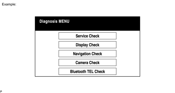
(2) Diagnosis MENU Screen
HINT:
Some items may be grayed out or not displayed, as the functions are different depending on the vehicle.
(3) Unit Check Mode Screen
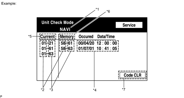
Screen Description
|
Display |
Contents |
|---|---|
|
*1: Device name |
Target device |
|
*2: Segment |
Target device logical address |
|
*3: DTC |
DTC (Diagnostic Trouble Code) |
|
*4: Timestamp |
Time and date of past DTCs are displayed (year is displayed in 2-digit format). |
|
*5: Present code |
DTCs output at service check are displayed. |
|
*6: Past code |
Diagnostic memory results and stored DTCs are output. |
|
*7: Diagnosis clear switch |
Pushing this switch for 3 seconds clears diagnostic memory data of target device (responses to diagnostic system check result and displayed data are cleared). |
(4) LAN Monitor (Original) Screen
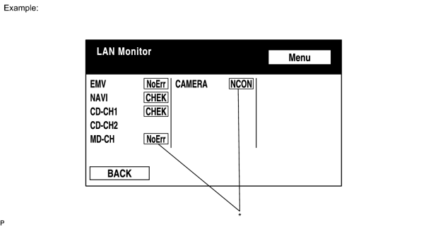
*: Check Result
HINT:
Check results of all the devices are displayed.
|
Result |
Meaning |
Action |
|---|---|---|
|
No Err (OK) |
There are no communication DTCs. |
- |
|
CHEK |
Device responds with "check" type DTC. |
Look up DTC in "Unit Check Mode". |
|
NCON |
Device was previously present, but does not respond in diagnostic mode. |
|
|
Old |
Device responds with "old" type DTC. |
Look up DTC in "Unit Check Mode". |
|
NRES |
Device responds in diagnostic mode, but gives no DTC information. |
|
(5) LAN Monitor (Individual) Screen
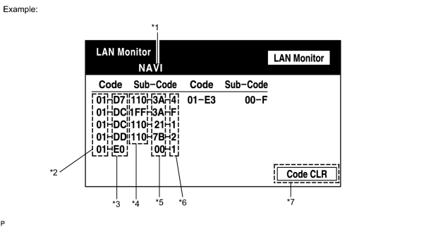
Screen Description
|
Display |
Contents |
|---|---|
|
*1: Device name |
Target device |
|
*2: Segment |
Target logical address |
|
*3: DTC |
DTC (Diagnostic Trouble Code) |
|
*4: Sub-code (device address) |
Physical address stored with DTC (if there is no address, nothing is displayed). |
|
*5: Connection check No. |
Connection check number stored with DTC. |
|
*6: DTC occurrence |
Number of times same DTC has been stored. |
|
*7: Diagnosis clear switch |
Pushing this switch for 3 seconds clears diagnostic memory data of target device (responses to diagnostic system check result and displayed data are cleared). |
(b) DISPLAY CHECK
(1) Vehicle Signal Check Mode Screen
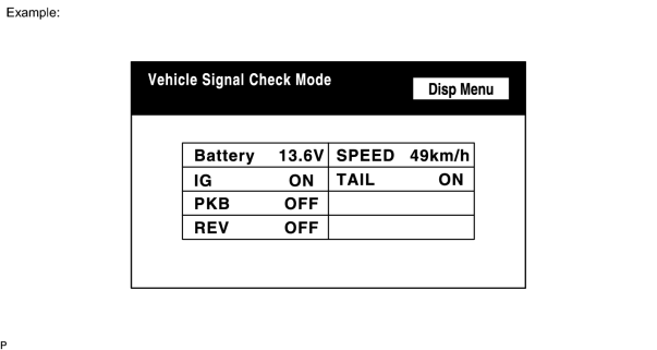
Screen Description
|
Name |
Contents |
|---|---|
|
Battery |
Battery voltage is displayed. |
|
PKB |
Parking brake ON/OFF state is displayed. |
|
REV |
Reverse signal ON/OFF state is displayed. |
|
IG |
Engine switch ON/OFF state is displayed. |
|
TAIL |
TAIL signal (Light control switch) ON/OFF state is displayed. |
|
SPEED |
Vehicle speed is displayed in km/h. |
HINT:
- Only items sending a vehicle signal will be displayed.
- This screen is updated once per second when input signals to the vehicle are changed.
(c) NAVIGATION CHECK
(1) Navigation Check Screen
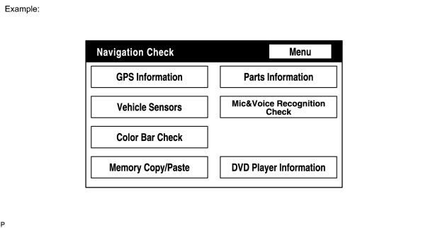
HINT:
Some items may be grayed out or not displayed, as the functions are different depending on the vehicle.
(2) GPS Information Screen
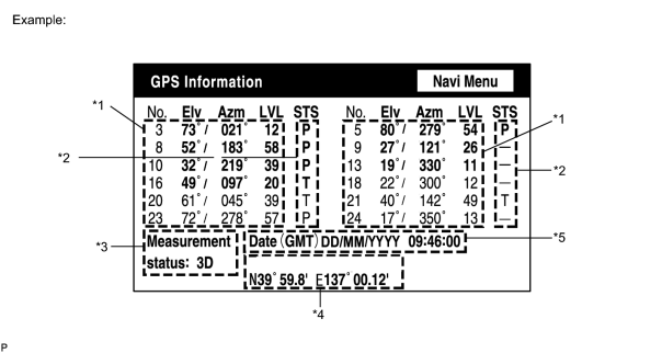
*1: Satellite information
Information from a maximum of 12 satellites is displayed on the screen. This information includes the target GPS satellite number, elevation angle, direction, and signal level.
*2: Receiving condition
DENSO Model
|
Display |
Contents |
|---|---|
|
T |
System is receiving GPS signal, but is not using it for location. |
|
P |
System is using GPS signal for location. |
|
- |
System cannot receive GPS signal. |
AISIN AW Model
|
Display |
Contents |
|---|---|
|
01H |
System cannot receive a GPS signal. |
|
02H |
System is tracing a satellite. |
|
03H |
System is receiving a GPS signal, but is not using it for location. |
|
04H |
System is using the GPS signal for location. |
*3: Measurement information
|
Display |
Contents |
|---|---|
|
2D |
2-dimensional location method is being used. |
|
3D |
3-dimensional location method is being used. |
|
NG |
Location data cannot be used. |
|
Error |
Reception error has occurred. |
|
- |
Any other state. |
*4: Position information
|
Display |
Contents |
|---|---|
|
Position |
Latitude and longitude information on current position is displayed. |
*5: Date information
|
Display |
Contents |
|---|---|
|
Date |
Date/time information obtained from GPS signal is displayed in Greenwich mean time (GMT). Last 4 digits are displayed. |
(3) Vehicle Sensors Screen
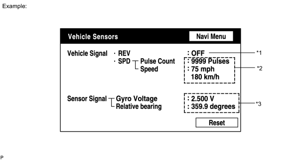
Vehicle Signal
|
Display |
Contents |
|---|---|
|
*1: REV |
REV signal ON/OFF state is displayed. |
|
*2: SPD |
SPD signal condition is displayed. |
Sensor Signal
|
Display |
Contents |
|---|---|
|
*3: Gyro sensor |
Gyro sensor output condition is displayed (when vehicle is driven straight or is stationary, voltage is approximately 2.5 V). |
HINT:
Signals are updated once per second only when vehicle sensor signals are changed.
(4) MICROPHONE & VOICE RECOGNITION CHECK Screen
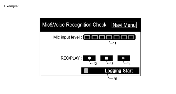
Screen Description
|
Display |
Contents |
|---|---|
|
*1: Microphone input level meter |
Monitors the microphone input level every 100 ms and displays results in 8 different levels. |
|
*2: Recording switch |
Starts recording. |
|
*3: Stop switch |
Stops recording. |
|
*4: Play switch |
Plays recorded voice. |
|
*5: Voice recognition logging start switch |
After this switch is turned on, when sound recognition occurs, up to 10 sounds are recorded (log is also recorded). |
HINT:
- The microphone input function is on at all times when this screen is displayed.
- While recording or playing, switches other than the stop switch cannot be pushed.
- When no voice is recorded, the play switch cannot be pushed.
- Recording will stop after 5 seconds or by pushing the stop switch.
(5) HDD Information Screen
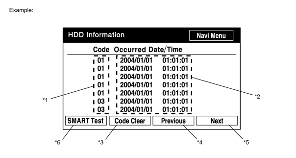
Screen Description
|
Display |
Contents |
|---|---|
|
*1: Trouble code |
Each code corresponding to malfunctions is output. For details, refer to "Trouble Code Description". |
|
*2: Occurrence time |
|
|
*3: Trouble code clear switch |
All code data being displayed is cleared by pushing this switch for 3 seconds. |
|
*4: Returning switch |
Previous page is displayed. If current displayed page is first page, this switch cannot be operated. |
|
*5: Proceeding switch |
Next page is displayed. If current displayed page is last page, this switch cannot be operated. |
|
*6: SMART test switch |
Perform SMART Test. After test ends, changes to SMART result display and SMART result is displayed. |
Trouble Code Description
|
Code |
Malfunction |
Countermeasure |
|---|---|---|
|
01 |
Cannot be recognized |
Replace navigation ECU. |
|
03 |
Cannot be read |
If map is not displayed, memory points are not recorded, or other symptoms occur, and this code is output frequently, replace display and navigation system (specified operation temperature: -20°C (-4°F) to 65°C (149°F)). |
|
04 |
Cannot write |
If map is not displayed, memory points are not recorded, or other symptoms occur, and this code is output frequently, replace display and navigation system (specified operation temperature: -20°C (-4°F) to 65°C (149°F)). |
|
13 |
Due to low temperature (-20°C (-4°F) or less), read operation cannot be performed. |
Turn engine switch on (IG), heat cabin, and check that display and navigation system temperature is sufficiently warmed up. |
|
14 |
Due to low temperature (-20°C (-4°F) or less), write operation cannot be performed. |
Turn engine switch on (IG), heat cabin, and check that display and navigation system temperature is sufficiently warmed up. |
|
23 |
Due to high temperature (65°C (149°F) or higher), read operation cannot be performed. |
Park vehicle in cool place. Check that temperature of display and navigation system has become sufficiently low, and that engine switch is on (ACC). |
|
24 |
Due to high temperature (65°C (149°F) or higher), write operation cannot be performed. |
Park vehicle in cool place. Check that temperature of display and navigation system has become sufficiently low, and that engine switch is on (ACC). |
HINT:
There is the HDD check function in the navigation ECU.
(6) SMART Test Screen
- In the HDD information screen, press the "SMART Test" button, and display the SMART Test result screen.
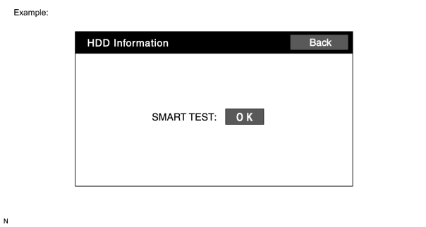
HINT:
- It takes approximately 90 seconds for the check to complete.
- If the SMART Test result is NG, the HDD is malfunctioning.
- If the temperature is low (below -20°C (-4°F)) or high (65°C (149°F) or higher), and the HDD cannot read or write, NG may be displayed.
(7) AVC-LAN Plus Check Screen
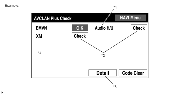
Screen Description
|
Display |
Contents |
|---|---|
|
*1: Device name |
Shows components connected to AVC-LAN plus. EMVN: Display and navigation module display Audio H/U: Radio receiver XM: Satellite radio tuner |
|
*2: Check result |
Shows AVC-LAN plus check result. OK: No DTCs CHECK: DTCs stored NCON: No connections |
|
*3: Detail |
Changes screen to DTC information screen. |
(8) AVC-LAN Plus Detail Screen
- This screen shows the number and time of reconfigurations.
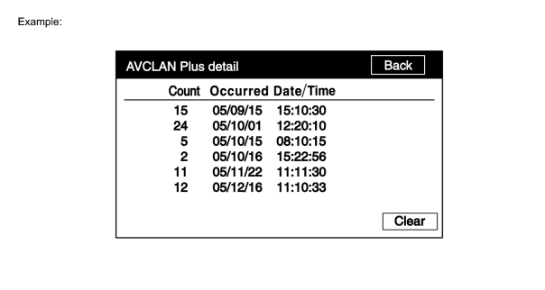
(9) AVC-LAN Plus Diagnosis Screen
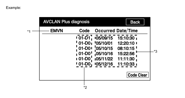
Screen Description
|
Display |
Contents |
|---|---|
|
*1: Device name |
Displays applicable components |
|
*2: DTC |
DTC (Diagnostic Trouble Code) |
|
*3: Occurrence time |
|
(10) Sound Library Information Screen
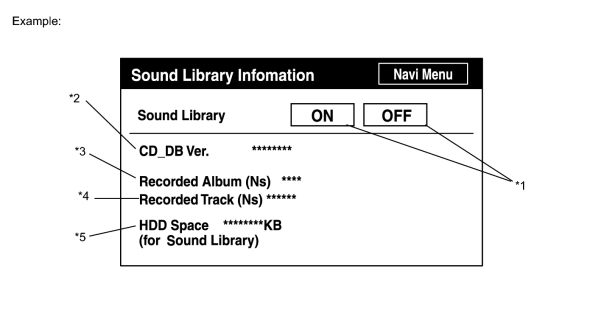
Screen Description
|
Display |
Contents |
|---|---|
|
*1: Switch for selecting HDD recording function |
ON: Recording possible OFF: Recording not possible |
|
*2: CD DB version |
Displays CD DB version |
|
*3: Number of albums |
Displays number of albums recorded to HDD |
|
*4: Number of recorded songs |
Displays number of songs recorded to HDD |
|
*5: Remaining space on HDD |
Displays remaining space on sound library part of HDD |
(d) PROGRAM UPDATE
(1) Program Update Screen
- This screen is used for program updates.
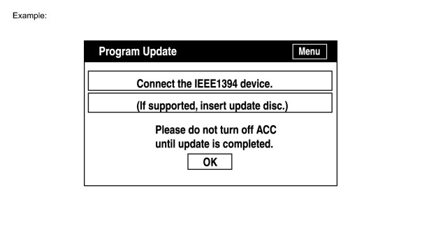
HINT:
For update procedures, view the new program disc contents and manual.

|

|