| Last Modified: 11-27-2007 | 1.6 J | |
| Service Category: Engine/Hybrid System | Section: Cruise Control | |
| Model Year: 2008 | Model: LX570 | Doc ID: RM000000PLU03GX |
| Title: CRUISE CONTROL: DYNAMIC RADAR CRUISE CONTROL SYSTEM: DESCRIPTION (2008 LX570) | ||
|
Cruise Control Switch Circuit |
DESCRIPTION
The cruise control main switch is used to operate 8 functions: SET, - (COAST), TAP-DOWN, RES (RESUME), + (ACCELERATION), TAP-UP, CANCEL and MODE. The SET, TAP-DOWN and - (COAST) functions, and the RES (RESUME), TAP-UP and + (ACCELERATION) functions are operated with the same switch. The cruise control main switch is an automatic return type switch which turns on only while operating it in each arrow direction and turns off after releasing it. The internal contact point of the cruise control main switch is turned on with the switch operation. Then the ECM reads the resistance value that has been changed by the switch operation to control MODE, SET, - (COAST), RES (RESUME), + (ACCELERATION) and CANCEL. The dynamic radar cruise control system has two cruise control modes: the constant speed control mode and vehicle-to-vehicle distance control mode.
HINT:
- The vehicle-to-vehicle distance control mode is always selected when starting up the dynamic radar cruise control system.
- The operation of the constant speed control mode is the same as the cruise control system.
WIRING DIAGRAM
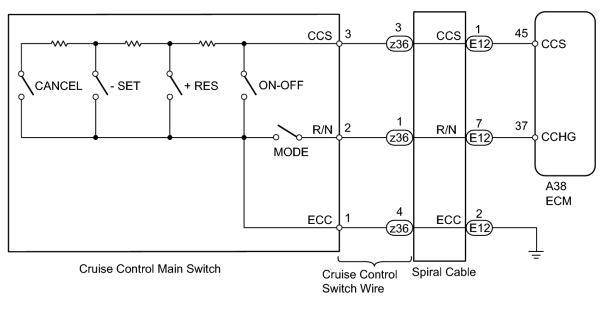
INSPECTION PROCEDURE
PROCEDURE
|
1. |
READ VALUE USING TECHSTREAM (CRUISE CONTROL MAIN SWITCH) |
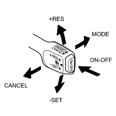
(a) Using the Techstream, read the Data List.
Radar Cruise
|
Tester Display |
Measurement Item/Range |
Normal Condition |
Diagnostic Note |
|---|---|---|---|
|
CCS Main SW M-CPU |
Cruise control main switch (Main CPU) / ON or OFF |
ON: Cruise control main switch (Main CPU) on OFF: Cruise control main switch (Main CPU) off |
- |
|
Cancel Switch |
CANCEL switch signal / ON or OFF |
ON: CANCEL switch on OFF: CANCEL switch off |
- |
|
SET/COAST Switch |
-SET switch signal / ON or OFF |
ON: -SET switch on OFF: -SET switch off |
- |
|
RES/ACC Switch |
+RES switch signal / ON or OFF |
ON: +RES switch on OFF: +RES switch off |
- |
|
CCS Main SW S-CPU |
Cruise control main switch (Sub CPU) / ON or OFF |
ON: Cruise control main switch (Sub CPU) on OFF: Cruise control main switch (Sub CPU) off |
- |
OK:
The Techstream display changes according to operation of cruise control main switch.
|

|
2. |
INSPECT CRUISE CONTROL MAIN SWITCH |
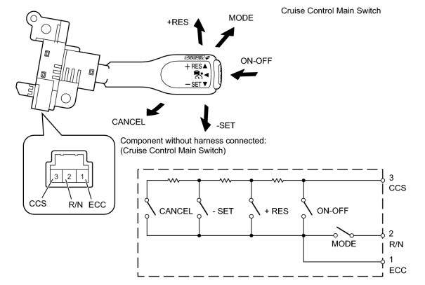
(a) Remove the cruise control main switch
 .
.
(b) Measure the resistance according to the value(s) in the table below.
Standard Resistance:
|
Tester Connection |
Switch Condition |
Specified Condition |
|---|---|---|
|
1 (ECC) - 3 (CCS) |
Neutral |
1 MΩ or higher |
|
Pushed to +RES |
235 to 245 Ω |
|
|
Pushed to -SET |
620 to 640 Ω |
|
|
Pushed to CANCEL |
1510 to 1570 Ω |
|
|
Main switch pushed off |
1 MΩ or higher |
|
|
Main switch pushed on |
Below 2.5 Ω |
|
|
1 (ECC) - 2 (R/N) |
MODE switch pushed on |
Below 2.5 Ω |
|
MODE switch off |
1 MΩ or higher |
|
|
3. |
INSPECT CRUISE CONTROL SWITCH WIRE |
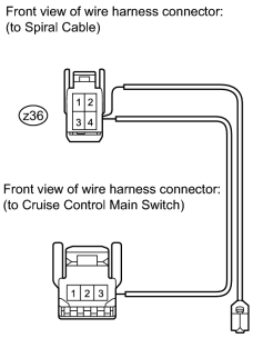
(a) Remove the cruise control switch wire.
(b) Measure the resistance according to the value(s) in the table below.
Standard Resistance:
|
Tester Connection |
Condition |
Specified Condition |
|---|---|---|
|
z36-3 - 3 |
Always |
Below 1 Ω |
|
z36-1 - 2 |
||
|
z36-4 - 1 |
||
|
z36-3 - Body ground |
Always |
10 kΩ or higher |
|
z36-1 - Body ground |
||
|
z36-4 - Body ground |
|
|
4. |
INSPECT SPIRAL CABLE |
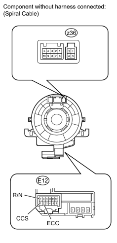
(a) Check the spiral cable and connector for scratches, cracks, dents and chips. If any defects are found, replace the spiral cable with a new one.
(b) Check the spiral cable.
(1) Set the spiral cable to the center position
.
(2) After setting the spiral cable to the center position, rotate the spiral cable 2.5 times clockwise, and measure the resistance according to the value(s) in the table below. Then rotate the spiral cable 5 times counterclockwise, and measure the resistance according to the value(s) in the table below.
Standard Resistance:
|
Tester Connection |
Condition |
Specified Condition |
|---|---|---|
|
z36-3 - E12-1 (CCS) |
Always |
Below 1 Ω |
|
z36-1 - E12-7 (R/N) |
||
|
z36-4 - E12-2 (ECC) |
(3) After setting the spiral cable to the center position, rotate the spiral cable 2.5 times clockwise. Then while rotating the spiral cable 5 times counterclockwise, measure the resistance according to the value(s) in the table below.
NOTICE:
As the spiral cable may break, do not rotate the spiral cable more than the specified amount.
Standard Resistance:
|
Tester Connection |
Condition |
Specified Condition |
|---|---|---|
|
z36-3 - E12-1 (CCS) |
Always |
Below 1 Ω |
|
z36-1 - E12-7 (R/N) |
||
|
z36-4 - E12-2 (ECC) |
|
|
5. |
CHECK HARNESS AND CONNECTOR (SPIRAL CABLE - ECM AND BODY GROUND) |
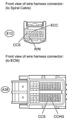
(a) Disconnect the E12 spiral cable connector.
(b) Disconnect the A38 ECM connector.
(c) Measure the resistance according to the value(s) in the table below.
Standard Resistance:
|
Tester Connection |
Condition |
Specified Condition |
|---|---|---|
|
E12-1 (CCS) - A38-45 (CCS) |
Always |
Below 1 Ω |
|
E12-7 (R/N) - A38-37 (CCHG) |
||
|
E12-1 (CCS) - Body ground |
Always |
10 kΩ or higher |
|
E12-7 (R/N) - Body ground |
||
|
E12-2 (ECC) - Body ground |
Always |
Below 1 Ω |
|

|

|