- Open or short in shift solenoid valve SLT circuit
- Shift solenoid valve SLT
- ECM
| Last Modified: 11-27-2007 | 1.6 C | |
| Service Category: Drivetrain | Section: Automatic Transmission/Transaxle | |
| Model Year: 2008 | Model: LX570 | Doc ID: RM000000W8A04TX |
| Title: AB60F AUTOMATIC TRANSMISSION / TRANSAXLE: AUTOMATIC TRANSMISSION SYSTEM: DESCRIPTION (2008 LX570) | ||
|
DTC |
P2716 |
Pressure Control Solenoid "D" Electrical (Shift Solenoid Valve SLT) |
DESCRIPTION
Refer to DTC P0894
 .
.
|
DTC Code |
DTC Detection Condition |
Trouble Area |
|---|---|---|
|
P2716 |
Conditions (a) or (b) below are detected for 1 sec. or more (1 trip detection logic). (a) Shift solenoid valve SLT - terminal: 0 V. (b) Shift solenoid valve SLT - terminal: 12 V. |
|
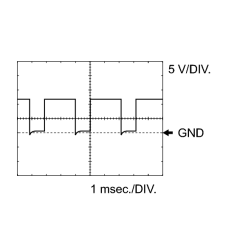
Reference: Inspect using an oscilloscope.
Check the waveform of the ECM connector.
Standard:
|
Terminal No. (Symbol) |
Tool Setting |
Condition |
Specified Condition |
|---|---|---|---|
|
C53-9 (SLT+) - C53-8 (SLT-) |
5 V/DIV., 1 msec./DIV. |
Engine idling |
Refer to illustration |
MONITOR DESCRIPTION
When an open or short in the shift solenoid valve SLT circuit is detected, the ECM interprets this as a fault. The ECM will turn on the MIL and store the DTC.
MONITOR STRATEGY
|
Related DTCs |
P2716: Shift solenoid valve SLT/Range check |
|
Required sensors/Components |
Shift solenoid valve SLT |
|
Frequency of operation |
Continuous |
|
Duration |
1 sec. |
|
MIL operation |
Immediately |
|
Sequence of operation |
None |
TYPICAL ENABLING CONDITIONS
All
|
The monitor will run whenever the following DTCs are not stored |
None |
|
Engine switch |
On (IG) |
|
Starter |
OFF |
Condition (A)
|
Solenoid current cut status |
Not cut |
|
Target current |
0.1 A or higher |
|
Battery voltage |
11 V or higher |
Condition (B)
|
Battery voltage |
8 V or higher |
TYPICAL MALFUNCTION THRESHOLDS
When either condition below is met: Condition (A) or (B)
Condition (A)
|
Solenoid status from Hybrid IC |
Failure |
Condition (B)
|
Hybrid IC status |
Failure |
COMPONENT OPERATING RANGE
|
Output signal duty |
Less than 100% |
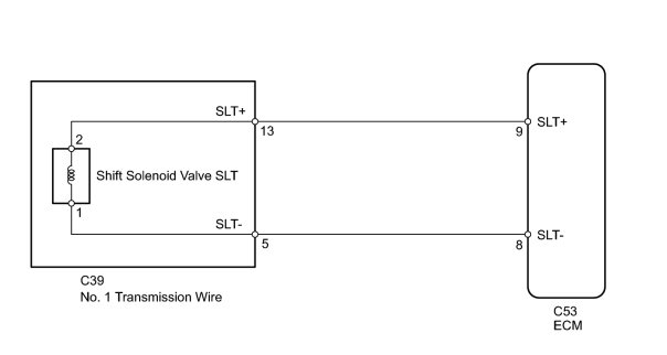
WIRING DIAGRAM
INSPECTION PROCEDURE
PROCEDURE
|
1. |
INSPECT NO. 1 TRANSMISSION WIRE (SHIFT SOLENOID VALVE SLT) |
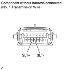
|
(a) Disconnect the C39 No. 1 transmission wire connector. |
(b) Measure the resistance according to the value(s) in the table below.
Standard Resistance:
|
Tester Connection |
Condition |
Specified Condition |
|---|---|---|
|
13 (SLT+) - 5 (SLT-) |
20°C (68°F) |
5.0 to 5.6 Ω |
|
13 (SLT+) - Body ground |
Always |
10 kΩ or higher |
|
5 (SLT-) - Body ground |
Always |
10 kΩ or higher |
|

|
2. |
CHECK HARNESS AND CONNECTOR (NO. 1 TRANSMISSION WIRE - ECM) |
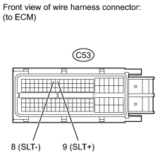
(a) Disconnect the C53 ECM connector.
(b) Measure the resistance according to the value(s) in the table below.
Standard Resistance:
|
Tester Connection |
Condition |
Specified Condition |
|---|---|---|
|
C53-9 (SLT+) - C53-8 (SLT-) |
20°C (68°F) |
5.0 to 5.6 Ω |
|
C53-9 (SLT+) - Body ground |
Always |
10 kΩ or higher |
|
C53-8 (SLT-) - Body ground |
Always |
10 kΩ or higher |
|
|
3. |
INSPECT SHIFT SOLENOID VALVE SLT |
(a) Remove shift solenoid valve SLT.
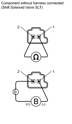
(b) Measure the resistance according to the value(s) in the table below.
Standard Resistance:
|
Tester Connection |
Condition |
Specified Condition |
|---|---|---|
|
1 - 2 |
20°C (68°F) |
5.0 to 5.6 Ω |
(c) Apply battery voltage (12 V) to the shift solenoid valve and check that the valve moves and makes an operating noise.
OK:
|
Measurement Condition |
Specified Condition |
|---|---|
|
Valve moves and makes an operating noise |
|

|

|