| Last Modified: 11-27-2007 | 1.6 J | |
| Service Category: Vehicle Interior | Section: Seat | |
| Model Year: 2008 | Model: LX570 | Doc ID: RM000000YCL00BX |
| Title: SEAT: FRONT POWER SEAT CONTROL SYSTEM: DESCRIPTION (2008 LX570) | ||
|
One or more Power Seat Motors do not Operate |
DESCRIPTION
When the front power seat switch is operated, a command signal is sent to the position control ECU. The position control ECU then controls the appropriate seat motor as needed. The position control ECU is designed so that a malfunction of the seat memory system will not interfere with manual seat control.
WIRING DIAGRAM
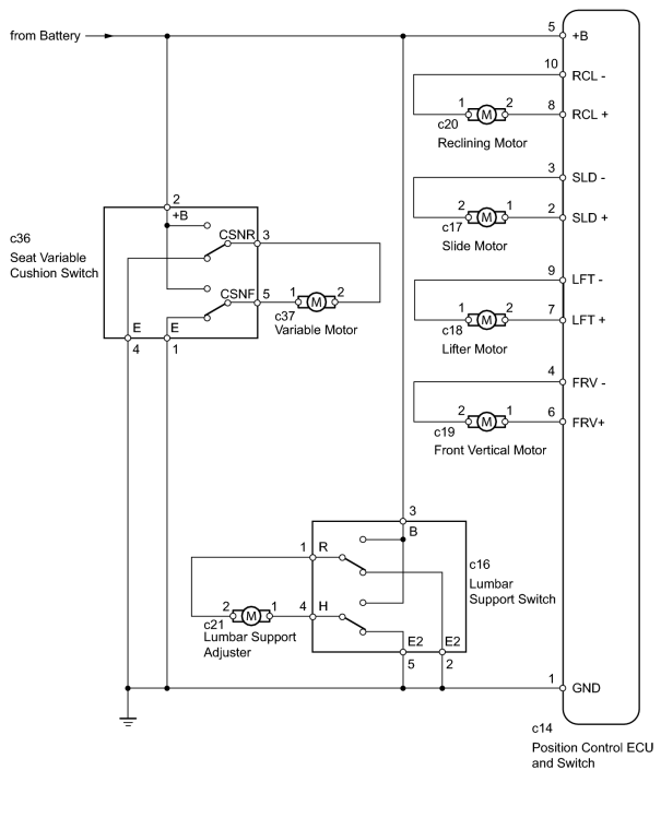
INSPECTION PROCEDURE
PROCEDURE
|
1. |
CHECK FRONT POWER SEAT OPERATION |
(a) Check that each function of the power seat operates normally by using the front power seat switches.
Result
|
Result |
Proceed to |
|---|---|
|
All front power seat switch operations are malfunctioning except lumbar support switch and seat variable cushion switch operation |
A |
|
Only lumbar support switch operation is malfunctioning |
B |
|
Only seat variable cushion switch operation is malfunctioning |
C |
|

|
2. |
READ VALUE USING TECHSTREAM (FRONT POWER SEAT SWITCH) |
(a) Using the Techstream, read the Data List.
Driver Seat
|
Tester Display |
Measurement Item/Range |
Normal Condition |
Diagnostic Note |
|---|---|---|---|
|
Reclining Rear |
Reclining switch signal (Rearward) / ON or OFF |
ON: Reclining switch (Rearward) on OFF: Reclining switch (Rearward) off |
- |
|
Reclining Front |
Reclining switch signal (Forward) / ON or OFF |
ON: Reclining switch (Forward) on OFF: Reclining switch (Forward) off |
- |
|
Front Vertical Down |
Front vertical switch signal (Downward) / ON or OFF |
ON: Front vertical switch (Downward) on OFF: Front vertical switch (Downward) off |
- |
|
Front Vertical Up |
Front vertical switch signal (Upward) / ON or OFF |
ON: Front vertical switch (Upward) on OFF: Front vertical switch (Upward) off |
- |
|
Lifter Switch Down |
Lifter switch signal (Downward) / ON or OFF |
ON: Lifter switch (Downward) on OFF: Lifter switch (Downward) off |
- |
|
Lifter Switch Up |
Lifter switch signal (Upward) / ON or OFF |
ON: Lifter switch (Upward) on OFF: Lifter switch (Upward) off |
- |
|
Slide Rear |
Sliding switch signal (Rearward) / ON or OFF |
ON: Sliding switch (Rearward) on OFF: Sliding switch (Rearward) off |
- |
|
Slide Front |
Sliding switch signal (Forward) / ON or OFF |
ON: Sliding switch (Forward) on OFF: Sliding switch (Forward) off |
- |
OK:
On the Techstream screen, each item changes between ON and OFF according to above chart.
|
|
3. |
PERFORM ACTIVE TEST USING TECHSTREAM (FRONT POWER SEAT MOTOR) |
(a) Using the Techstream, perform the Active Test.
Driver Seat
|
Tester Display |
Test Part |
Control Range |
Diagnostic Note |
|---|---|---|---|
|
Seat Reclining |
Seat reclining operation |
Front / OFF / Rear |
- |
|
Front Vertical Operation |
Seat front vertical operation |
Up / OFF / Down |
- |
|
Lifter Operation |
Seat lifter operation |
Up / OFF / Down |
- |
|
Seat Slide Operation |
Seat sliding operation |
Front / OFF / Rear |
- |
OK:
The power seat motors operate normally.
|
|
4. |
INSPECT FRONT SEAT ASSEMBLY LH (FRONT POWER SEAT MOTOR) |
(a) Remove the front seat assembly LH
 .
.
|
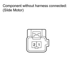
(b) Check operation of the slide motor. (1) Check if the seat moves smoothly when the battery is connected to the slide motor connector terminals. OK:
|
|
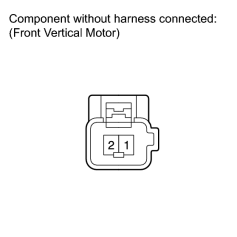
(c) Check operation of the front vertical motor. (1) Check if the seat moves smoothly when the battery is connected to the front vertical motor connector terminals. OK:
|

|
(d) Check operation of the lifter motor. (1) Check if the seat moves smoothly when the battery is connected to the lifter motor connector terminals. OK:
|
|
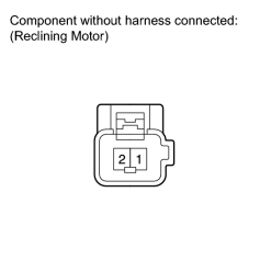
(e) Check operation of the reclining motor. (1) Check if the seat moves smoothly when the battery is connected to the reclining motor connector terminals. OK:
|
|
|
5. |
CHECK HARNESS AND CONNECTOR (POSITION CONTROL ECU AND SWITCH - POWER SEAT MOTOR) |
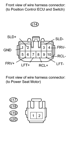
(a) Disconnect the c14 switch connector.
(b) Disconnect the c17, c18, c19 and c20 motor connectors.
(c) Measure the resistance according to the value(s) in the table below.
Standard Resistance:
|
Tester Connection |
Condition |
Specified Condition |
|---|---|---|
|
c14-3 (SLD-) - c17-2 |
Always |
Below 1 Ω |
|
c14-2 (SLD+) - c17-1 |
Always |
Below 1 Ω |
|
c14-4 (FRV-) - c19-2 |
Always |
Below 1 Ω |
|
c14-6 (FRV+) - c19-1 |
Always |
Below 1 Ω |
|
c14-9 (LFT-) - c18-1 |
Always |
Below 1 Ω |
|
c14-7 (LFT+) - c18-2 |
Always |
Below 1 Ω |
|
c14-10 (RCL-) - c20-1 |
Always |
Below 1 Ω |
|
c14-8 (RCL+) - c20-2 |
Always |
Below 1 Ω |
|
c14-1 (GND) - Body ground |
Always |
Below 1 Ω |
|
c14-3 (SLD-) or c17-2 - Body ground |
Always |
10 kΩ or higher |
|
c14-2 (SLD+) or c17-1 - Body ground |
Always |
10 kΩ or higher |
|
c14-4 (FRV-) or c19-2 - Body ground |
Always |
10 kΩ or higher |
|
c14-6 (FRV+) or c19-1 - Body ground |
Always |
10 kΩ or higher |
|
c14-9 (LFT-) or c18-1 - Body ground |
Always |
10 kΩ or higher |
|
c14-7 (LFT+) or c18-2 - Body ground |
Always |
10 kΩ or higher |
|
c14-10 (RCL-) or c20-1 - Body ground |
Always |
10 kΩ or higher |
|
c14-8 (RCL+) or c20-2 - Body ground |
Always |
10 kΩ or higher |
|
|
6. |
INSPECT LUMBAR SUPPORT SWITCH |
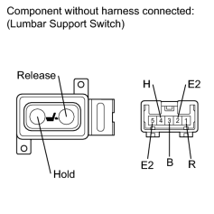
(a) Remove the lumbar support switch
.
(b) Measure the resistance according to the value(s) in the table below.
Standard Resistance:
|
Tester Connection |
Switch Condition |
Specified Condition |
|---|---|---|
|
3 (B) - 4 (H) |
Hold |
Below 1 Ω |
|
1 (R) - 2 (E2) |
||
|
4 (H) - 5 (E2) |
Off |
|
|
1 (R) - 2 (E2) |
||
|
4 (H) - 5 (E2) |
Release |
|
|
1 (R) - 3 (B) |
|
|
7. |
INSPECT LUMBAR SUPPORT ADJUSTER ASSEMBLY |
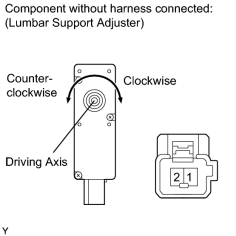
(a) Remove the lumbar support adjuster
.
(b) Check operation of the lumbar support adjuster.
(1) Check that the lumbar support adjuster moves smoothly when the battery is connected to the lumbar support adjuster motor connector terminals.
OK:
|
Measurement Condition |
Specified Condition |
|---|---|
|
Battery positive (+) → 1 Battery negative (-) → 2 |
Clockwise |
|
Battery positive (+) → 2 Battery negative (-) → 1 |
Counterclockwise |
|
|
8. |
CHECK HARNESS AND CONNECTOR (LUMBAR SUPPORT SWITCH - BATTERY AND BODY GROUND) |
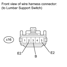
(a) Disconnect the c16 switch connector.
(b) Measure the voltage according to the value(s) in the table below.
Standard Voltage:
|
Tester Connection |
Condition |
Specified Condition |
|---|---|---|
|
c16-3 (B) - Body ground |
Always |
11 to 14 V |
(c) Measure the resistance according to the value(s) in the table below.
Standard Resistance:
|
Tester Connection |
Condition |
Specified Condition |
|---|---|---|
|
c16-5 (E2) - Body ground |
Always |
Below 1 Ω |
|
c16-2 (E2) - Body ground |
|
|
15. |
INSPECT SEAT VARIABLE CUSHION SWITCH |
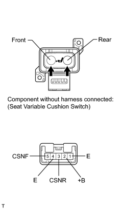
(a) Remove the seat variable cushion switch
.
(b) Measure the resistance according to the value(s) in the table below.
Standard Resistance:
|
Tester Connection |
Switch Condition |
Specified Condition |
|---|---|---|
|
2 (+B) - 5 (CSNF) |
Front |
Below 1 Ω |
|
3 (CSNR) - 4 (E) |
||
|
3 (CSNR) - 4 (R) |
Off |
|
|
1 (E) - 5 (CSNF) |
||
|
2 (+B) - 3 (CSNR) |
Rear |
|
|
1 (E) - 5 (CSNF) |
|
|
16. |
INSPECT FRONT SEAT ASSEMBLY LH (VARIABLE MOTOR) |
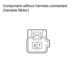
(a) Remove the front seat assembly LH
.
(b) Check operation of the variable motor.
(1) Check if the seat cushion moves smoothly when the battery is connected to the variable motor connector terminals.
OK:
|
Measurement Condition |
Specified Condition |
|---|---|
|
Battery positive (+) → 1 Battery negative (-) → 2 |
Forward |
|
Battery positive (+) → 2 Battery negative (-) → 1 |
Rearward |
|
|
17. |
CHECK HARNESS AND CONNECTOR (SEAT VARIABLE CUSHION SWITCH - BATTERY AND BODY GROUND) |

(a) Disconnect the c36 switch connector.
(b) Measure the voltage according to the value(s) in the table below.
Standard Voltage:
|
Tester Connection |
Condition |
Specified Condition |
|---|---|---|
|
c36-2 (+B) - Body ground |
Always |
11 to 14 V |
(c) Measure the resistance according to the value(s) in the table below.
Standard Resistance:
|
Tester Connection |
Condition |
Specified Condition |
|---|---|---|
|
c36-1 (E) - Body ground |
Always |
Below 1 Ω |
|
c36-4 (E) - Body ground |
|

|

|