- The input voltage to the ECM remains at below 0.3 V or higher than 4.7 V for more than 4 seconds when 2 or more seconds have elapsed after turning the engine switch on (IG) (1 trip detection logic).
- No VVT sensor signal is sent to the ECM during cranking (2 trip detection logic).
| Last Modified: 11-27-2007 | 1.6 C | |
| Service Category: Engine/Hybrid System | Section: Engine Control | |
| Model Year: 2008 | Model: LX570 | Doc ID: RM000000YTB02UX |
| Title: 3UR-FE ENGINE CONTROL: SFI SYSTEM: DESCRIPTION (2008 LX570) | ||
|
DTC |
P0365 |
Camshaft Position Sensor "B" Circuit (Bank 1) |
|
DTC |
P0367 |
Camshaft Position Sensor "B" Circuit Low Input (Bank 1) |
|
DTC |
P0368 |
Camshaft Position Sensor "B" Circuit High Input (Bank 1) |
|
DTC |
P0390 |
Camshaft Position Sensor "B" Circuit (Bank 2) |
|
DTC |
P0392 |
Camshaft Position Sensor "B" Circuit Low Input (Bank 2) |
|
DTC |
P0393 |
Camshaft Position Sensor "B" Circuit High Input (Bank 2) |
DESCRIPTION
The exhaust camshaft Variable Valve Timing (VVT) sensor (EV1, 2 signal) consists of a magnet and MRE (Magnetic Resistance Element).
The exhaust camshaft has 3 teeth on its outer circumference. When the exhaust camshaft rotates, changes occur in the air gaps between the teeth and MRE, which affects the magnetic field. As a result, the resistance of the MRE material fluctuates. The VVT sensor converts the exhaust camshaft rotation data into pulse signals, uses the pulse signals to determine the camshaft angle, and sends it to the ECM.
|
DTC Code |
DTC Detection Condition |
Trouble Area |
|---|---|---|
|
P0365 P0390 |
When either condition below is met: |
|
|
P0367 P0392 |
The output voltage of the VVT sensor is below 0.3 V for 4 seconds (1 trip detection logic). |
|
|
P0368 P0393 |
The output voltage of the VVT sensor is higher than 4.7 V for 4 seconds (1 trip detection logic). |
|
Reference: Inspection using an oscilloscope
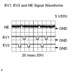
Standard:
|
Tester Connection |
Tool Setting |
Condition |
Specified Condition |
|---|---|---|---|
|
C53-110 (NE+) - C53-111 (NE-) |
5 V/DIV. 20 msec./DIV. |
Cranking or idling |
The correct waveform is as shown |
|
C53-69 (EV1+) - C53-68 (EV1-) |
5 V/DIV. 20 msec./DIV. |
Cranking or idling |
The correct waveform is as shown |
|
C53-64 (EV2+) - C53-65 (EV2-) |
5 V/DIV. 20 msec./DIV. |
Cranking or idling |
The correct waveform is as shown |
HINT:
EV1+ and EV2+ stand for the VVT sensor (for exhaust side) signal, and NE+ stands for the CKP sensor signal.
MONITOR DESCRIPTION
If no signal is transmitted by the VVT sensor despite the engine revolving, or the rotations of the camshaft and the crankshaft are not synchronized, the ECM interprets this as a malfunction of the sensor.
MONITOR STRATEGY
|
Related DTCs |
P0365: VVT sensor (for Bank 1) open/short P0365: VVT position/Crankshaft position misalignment (for Bank 1) P0367: VVT position sensor (for Bank 1) range check (low voltage) P0368: VVT position sensor (for Bank 1) range check (high voltage) P0390: VVT sensor (for Bank 2) open/short P0390: VVT position/Crankshaft position misalignment (for Bank 2) P0392: VVT position sensor (for Bank 2) range check (low voltage) P0393: VVT position sensor (for Bank 2) range check (high voltage) |
|
Required Sensors/Components (Main) |
VVT position sensor (for Bank 1 and 2) |
|
Required Sensors/Components (Related) |
Crankshaft position sensor |
|
Frequency of Operation |
Continuous |
|
Duration |
5 seconds: P0365, P0390 (After starting engine) 4 seconds: Others |
|
MIL Operation |
2 driving cycles: P0365, P0390 (cranking) Immediate: Others |
|
Sequence of Operation |
None |
TYPICAL ENABLING CONDITIONS
All:
|
Monitor runs whenever following DTCs are not stored |
None |
Chattering, Low voltage, High voltage:
|
Starter |
OFF |
|
Engine switch |
On (IG) |
|
Time after engine switch off to on (IG) |
2 seconds or more |
|
Battery voltage |
8 V or higher |
P0365, P0390 (Engine running):
|
Engine speed |
600 rpm or more |
|
Battery voltage |
8 V or higher |
|
Starter |
OFF |
|
Engine switch |
On (IG) |
P0365, P0390 (Cranking):
|
Starter |
ON |
|
Minimum battery voltage |
Below 11 V |
TYPICAL MALFUNCTION THRESHOLDS
P0365, P0390 (Chattering):
|
Exhaust VVT sensor voltage |
Below 0.3 V, or higher than 4.7 V |
P0367, P0392 (Low voltage):
|
Exhaust VVT sensor voltage |
Below 0.3 V |
P0368, P0393 (High voltage):
|
Exhaust VVT sensor voltage |
Higher than 4.7 V |
P0365, P0390 (Engine running, Cranking):
|
Exhaust VVT sensor signal |
No signal |
COMPONENT OPERATING RANGE
|
VVT sensor voltage |
0.3 to 4.7 V |
WIRING DIAGRAM
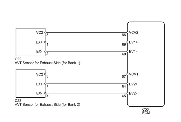
INSPECTION PROCEDURE
HINT:
Read freeze frame data using the Techstream. Freeze frame data records the engine condition when malfunctions are detected. When troubleshooting, freeze frame data can help determine if the vehicle was moving or stationary, if the engine was warmed up or not, if the air-fuel ratio was lean or rich, and other data from the time the malfunction occurred.
PROCEDURE
|
1. |
CHECK HARNESS AND CONNECTOR (SENSOR POWER SOURCE) |
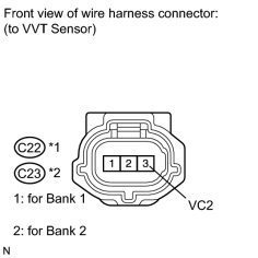
|
(a) Disconnect the C22 or C23 VVT sensor (for exhaust side) connector. |
(b) Measure the voltage according to the value(s) in the table below.
Standard Voltage:
|
Tester Connection |
Condition |
Specified Condition |
|---|---|---|
|
3 (VC2) - Body ground |
Engine switch on (IG) |
4.5 to 5.0 V |
|

|
2. |
CHECK HARNESS AND CONNECTOR (VVT SENSOR (for Exhaust Side) - ECM) |
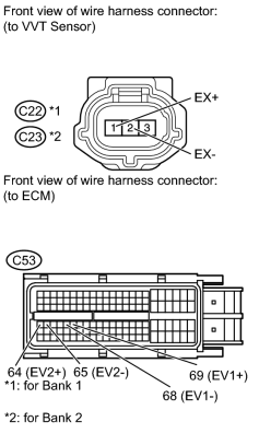
|
(a) Disconnect the C22 or C23 VVT (for exhaust side) sensor connector. |
(b) Disconnect the C53 ECM connector.
(c) Measure the resistance according to the value(s) in the table below.
Standard Resistance:
|
Tester Connection |
Condition |
Specified Condition |
|---|---|---|
|
C22-1 (EX+) - C53-69 (EV1+) |
Always |
Below 1 Ω |
|
C22-2 (EX-) - C53-68 (EV1-) |
Always |
Below 1 Ω |
|
C23-1 (EX+) - C53-64 (EV2+) |
Always |
Below 1 Ω |
|
C23-2 (EX-) - C53-65 (EV2-) |
Always |
Below 1 Ω |
|
C22-1 (EX+) or C53-69 (EV1+) - Body ground |
Always |
10 kΩ or higher |
|
C22-2 (EX-) or C53-68 (EV1-) - Body ground |
Always |
10 kΩ or higher |
|
C23-1 (EX+) or C53-64 (EV2+) - Body ground |
Always |
10 kΩ or higher |
|
C23-2 (EX-) or C53-65 (EV2-) - Body ground |
Always |
10 kΩ or higher |
|
|
3. |
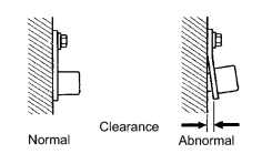
CHECK SENSOR INSTALLATION (VVT SENSOR) |
|
(a) Check the VVT sensor (for exhaust side) installation. OK: Sensor is installed correctly. |
|
|
4. |
CHECK EXHAUST CAMSHAFT |
(a) Check the teeth of the camshaft.
OK:
Teeth do not have any cracks or deformation.
|
|
5. |
REPLACE VVT SENSOR (for Exhaust Side) |
(a) Replace the VVT sensor (for exhaust side)
 .
.
|
|
6. |
CHECK WHETHER DTC OUTPUT RECURS |
(a) Connect the Techstream to the DLC3.
(b) Turn the engine switch on (IG).
(c) Turn the Techstream on.
(d) Clear DTCs
.
(e) Start the engine.
(f) Enter the following menus: Powertrain / Engine and ECT / Trouble Codes.
(g) Read DTCs.
Result
|
Result |
Proceed to |
|---|---|
|
No output |
A |
|
P0365, P0367, P0368, P0390, P0392 or P0393 |
B |
HINT:
If the engine does not start, replace the ECM.
|

|

|