| Last Modified: 11-27-2007 | 1.6 U | |
| Service Category: Audio/Visual/Telematics | Section: Audio/Video | |
| Model Year: 2008 | Model: LX570 | Doc ID: RM0000011BQ037X |
| Title: AUDIO / VIDEO: AUDIO AND VISUAL SYSTEM: TERMINALS OF ECU (2008 LX570) | ||
TERMINALS OF ECU
1. CHECK DISPLAY AND NAVIGATION MODULE DISPLAY*1, MULTI-DISPLAY*2
- *1: w/ Navigation System
- *2: w/o Navigation System
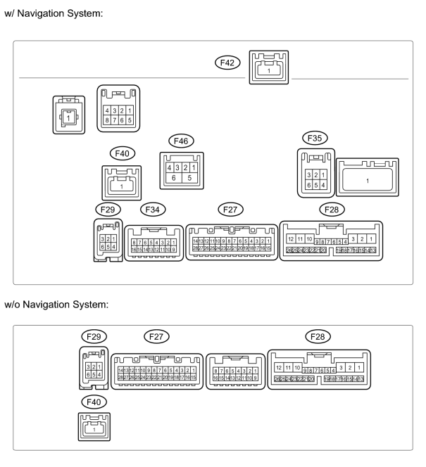
(a) Disconnect the F28 display connector.
(b) Measure the resistance and voltage according to the value(s) in the table below.
|
Terminal No. (Symbol) |
Wiring Color |
Terminal Description |
Condition |
Specified Condition |
|---|---|---|---|---|
|
F28-1 (+B1) - F28-10 (GND1) |
R - W-B |
Battery |
Always |
11 to 14 V |
|
F28-2 (ACC) - F28-10 (GND1) |
GR - W-B |
Accessory (ON) |
Engine switch off |
Below 1 V |
|
F28-2 (ACC) - F28-10 (GND1) |
GR - W-B |
Accessory (ON) |
Engine switch on (ACC) |
11 to 14 V |
|
F28-3 (IG) - F28-10 (GND1) |
G - W-B |
Ignition (ON) |
Engine switch off |
Below 1 V |
|
F28-3 (IG) - F28-10 (GND1) |
G - W-B |
Ignition (ON) |
Engine switch on (IG) |
11 to 14 V |
|
F28-10 (GND1) - Body ground |
W-B - Body ground |
Ground |
Always |
Below 1 Ω |
If the result is not as specified, there may be a malfunction on the wire harness side.
(c) Reconnect the F28 display connector.
(d) Measure the voltage according to the value(s) in the table below.
|
Terminal No. (Symbol) |
Wiring Color |
Terminal Description |
Condition |
Specified Condition |
|---|---|---|---|---|
|
F27-1 (TX-) - F28-10 (GND1) |
L - B-W |
AVC-LAN communication signal |
Engine switch on (ACC) |
2 to 3 V |
|
F27-2 (TX+) - F28-10 (GND1) |
W - B-W |
AVC-LAN communication signal |
Engine switch on (ACC) |
2 to 3 V |
|
F27-3 (TX2-) - F28-10 (GND1) |
L - W-B |
AVC-LAN communication signal |
Engine switch on (ACC) |
2 to 3 V |
|
F27-4 (TX2+) - F28-10 (GND1) |
W - W-B |
AVC-LAN communication signal |
Engine switch on (ACC) |
2 to 3 V |
|
F27-5 (TSW-) - F28-10 (GND1) |
BR - W-B |
Telephone relation switch signal |
Always |
Below 1 V |
|
F27-9 (MACC) - F28-10 (GND1)*1 |
Y - W-B |
Microphone amplifier power supply |
Engine switch off |
Below 1 V |
|
F27-9 (MACC) - F28-10 (GND1)*1 |
Y - W-B |
Microphone amplifier power supply |
Engine switch on (IG) |
5 V |
|
F27-10 (MIN-) - F28-10 (GND1) |
R - W-B |
Microphone voice signal |
See "Mic & Voice Recognition Check"
|
- |
|
F27-11 (MIN+) - F28-10 (GND1) |
G - W-B |
Microphone voice signal |
See "Mic & Voice Recognition Check"
|
- |
|
F27-12 (SGND) - F28-10 (GND1) |
BR - W-B |
Signal ground |
Always |
Below 1 V |
|
F27-13 (CA+) - F28-10 (GND1)*2 |
B - W-B |
Television camera power supply |
Engine switch on (IG), shift lever moved to R |
5.8 to 6.5 V |
|
F27-14 (CGND) - Body ground*2 |
W - Body ground |
Ground |
Always |
Below 1 V |
|
F27-21 (IVO-) - F28-10 (GND1) |
B - W-B |
Voice guidance signal |
Voice guidance provided |
Waveform synchronized with sounds is output |
|
F27-22 (IVO+) - F28-10 (GND1) |
W - W-B |
Voice guidance signal |
Voice guidance provided |
Waveform synchronized with sounds is output |
|
F27-23 (SLD) - F28-10 (GND1) |
Shielded - W-B |
Shielded ground |
Always |
Below 1 V |
|
F27-27 (V+) - F27-14 (CGND)*2 |
R - W |
Television camera image signal |
Engine switch on (IG), shift lever moved to R |
Pulse generation (refer to waveform 1) |
|
F27-28 (V-) - F27-14 (CGND)*2 |
Shielded - W |
Shielded ground |
Always |
Below 1 V |
|
F28-5 (HILL) - F28-10 (GND1) |
W - W-B |
Illumination signal |
Light control switch off |
Below 1 V |
|
F28-5 (HILL) - F28-10 (GND1) |
W - W-B |
Illumination signal |
Light control switch on |
11 to 14 V |
|
F28-7 (TC) - F28-10 (GND1) |
V - W-B |
Diagnosis ON signal |
Engine switch on (IG) |
9 to 14 V |
|
F28-8 (HAZ) - F28-10 (GND1) |
O - W-B |
Hazard warning signal |
Hazard warning switch off |
Below 1 V |
|
Hazard warning switch on |
11 to 14 V |
|||
|
F28-9 (ARON) - F28-10 (GND1) |
W - W-B |
Front passenger side airbag ON/OFF indicator signal |
Passenger airbag ON/OFF indicator off |
Below 2 V |
|
Passenger airbag ON/OFF indicator on |
11 to 14 V |
|||
|
F28-12 (ILL+) - F28-10 (GND1) |
G - W-B |
Illumination signal |
Light control switch off |
Below 1 V |
|
F28-12 (ILL+) - F28-10 (GND1) |
G - W-B |
Illumination signal |
Light control switch on |
11 to 14 V |
|
F28-13 (REV) - F28-10 (GND1) |
L - W-B |
Reverse signal |
See "Vehicle Signal Check" Mode
|
- |
|
F28-14 (SPD) - F28-10 (GND1) |
V - W-B |
Speed signal from combination meter |
See "Vehicle Signal Check" Mode
|
- |
|
F28-20 (AIR) - F28-10 (GND1) |
B - W-B |
Front passenger side airbag ON/OFF indicator signal |
Passenger airbag ON/OFF indicator off |
Below 2 V |
|
Passenger airbag ON/OFF indicator on |
10.5 to 16 V |
|||
|
F28-21 (PBEW) - F28-10 (GND1) |
Y - W-B |
Passenger seat belt signal |
Passenger seat occupied, seat belt fastened |
11 to 14 V |
|
Passenger seat occupied, seat belt unfastened |
Below 2 V |
|||
|
F28-23 (PKB) - F28-10 (GND1) |
Y - W-B |
Parking brake signal |
See "Vehicle Signal Check" Mode
|
- |
|
F28-24 (HFOF) - F28-10 (GND1) |
B - W-B |
Phone mute |
Engine switch on (IG) |
3.3 to 5.0 V |
|
F29-1 (VV+) - F28-10 (GND1) |
W - W-B |
DVD image signal |
DVD played on radio receiver |
Pulse generation (refer to waveform 2) |
|
F29-4 (VV-) - F28-10 (GND1) |
B - W-B |
Signal ground |
Always |
Below 1 V |
|
F34-1 (FR+) - F28-10 (GND1)*3, *4, *5 |
B - W-B |
Sound signal (right) |
Engine switch on (ACC), audio system playing |
Waveform synchronized with sounds is output |
|
F34-2 (FR-) - F28-10 (GND1)*3, *4, *5 |
W - W-B |
Sound signal (right) |
Engine switch on (ACC), audio system playing |
Waveform synchronized with sounds is output |
|
F34-3 (FL+) - F28-10 (GND1)*3, *4, *5 |
L - W-B |
Sound signal (left) |
Engine switch on (ACC), audio system playing |
Waveform synchronized with sounds is output |
|
F34-4 (FL-) - F28-10 (GND1)*3, *4, *5 |
R - W-B |
Sound signal (left) |
Engine switch on (ACC), audio system playing |
Waveform synchronized with sounds is output |
|
F34-5 (SLD1) - F28-10 (GND1)*3, *4, *5 |
Shielded - W-B |
Shielded ground |
Always |
Below 1 V |
|
F34-7 (MUT2) - F28-10 (GND1)*3, *5 |
B - W-B |
Mute signal |
Sound library playing → Changing mode |
3.5 V or higher → Below 1 V |
|
F34-8 (MUTE) - F28-10 (GND1)*3, *4, *5 |
G - W-B |
Mute signal |
Sound library playing → Changing mode |
3.5 V or higher → Below 1 V |
|
F34-9 (RL-) - F28-10 (GND1)*3, *5 |
G - W-B |
Sound signal (right) |
Engine switch on (ACC), audio system playing |
Waveform synchronized with sounds is output |
|
F34-10 (RL+) - F28-10 (GND1)*3, *5 |
R - W-B |
Sound signal (right) |
Engine switch on (ACC), audio system playing |
Waveform synchronized with sounds is output |
|
F34-11 (RR-) - F28-10 (GND1)*3, *5 |
W - W-B |
Sound signal (left) |
Engine switch on (ACC), audio system playing |
Waveform synchronized with sounds is output |
|
F34-12 (RR+) - F28-10 (GND1)*3, *5 |
B - W-B |
Sound signal (left) |
Engine switch on (ACC), audio system playing |
Waveform synchronized with sounds is output |
|
F34-13 (SGD2) - F28-10 (GND1)*3, *5 |
Shielded - W-B |
Shielded ground |
Always |
Below 1 V |
|
F35-2 (TXO+) - F28-10 (GND1)*5 |
B - B-W |
AVC-LAN plus communication signal |
Engine switch on (ACC) |
- |
|
F35-3 (TXI+) - F28-10 (GND1)*5 |
B - B-W |
AVC-LAN plus communication signal |
Engine switch on (ACC) |
- |
|
F35-5 (TXO-) - F28-10 (GND1)*5 |
W - B-W |
AVC-LAN plus communication signal |
Engine switch on (ACC) |
- |
|
F35-6 (TXI-) - F28-10 (GND1)*5 |
W - B-W |
AVC-LAN plus communication signal |
Engine switch on (ACC) |
- |
|
F40-1 (GVIF) - F28-10 (GND1)*2 |
B - B-W |
Digital image signal |
- |
- |
|
F42-1 (GVIF) - F28-10 (GND1)*3, *5 |
B - B-W |
Digital image signal |
- |
- |
|
F46-1 (IEEE) - F28-10 (GND1)*5 |
B - W-B |
IEEE signal |
Engine switch on (ACC) |

If the result is not as specified, the display and navigation module display or multi-display may have a malfunction.
*1: w/o LEXUS Link System
*2: w/ Wide View Front and Side Monitor System
*3: for DVD Changer Models
*4: w/ SDARS System
*5: w/ Navigation System
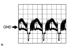
|
(e) Using an oscilloscope, check waveform 1.
|
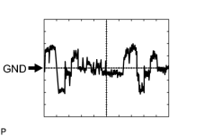
|
(f) Using an oscilloscope, check waveform 2.
|
2. CHECK RADIO RECEIVER (for DVD Changer Models)
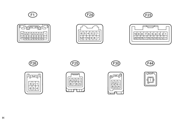
(a) Disconnect the F1 receiver connector.
(b) Measure the resistance and voltage according to the value(s) in the table below.
|
Terminal No. (Symbol) |
Wiring Color |
Terminal Description |
Condition |
Specified Condition |
|---|---|---|---|---|
|
F1-1 (B) - F1-20 (GND) |
L - BR |
Battery |
Always |
11 to 14 V |
|
F1-20 (GND) - Body ground |
BR - Body ground |
Ground |
Always |
Below 1 Ω |
|
F1-11 (ACC) - F1-20 (GND) |
GR - BR |
Accessory (ON) |
Engine switch off |
Below 1 V |
|
F1-11 (ACC) - F1-20 (GND) |
GR - BR |
Accessory (ON) |
Engine switch on (ACC) |
11 to 14 V |
If the result is not as specified, there may be a malfunction on the wire harness side.
(c) Reconnect the F1 receiver connector.
(d) Measure the resistance, waveform and voltage according to the value(s) in the table below.
|
Terminal No. (Symbol) |
Wiring Color |
Terminal Description |
Condition |
Specified Condition |
|---|---|---|---|---|
|
F1-2 (ILL+) - F1-20 (GND) |
G - BR |
Illumination signal |
Engine switch on (IG), light control switch off |
Below 1 V |
|
F1-2 (ILL+) - F1-20 (GND) |
G - BR |
Illumination signal |
Engine switch on (IG), light control switch tail or on |
11 to 14 V |
|
F1-7 (MUTE) - F1-20 (GND) |
B - BR |
Mute signal |
Audio system playing → changing modes |
3.5 V or higher → Below 1 V |
|
F1-8 (R+) - F1-20 (GND) |
B - BR |
Sound signal (right) |
Audio system playing |
Waveform synchronized with sound is output |
|
F1-9 (L+) - F1-20 (GND) |
R - BR |
Sound signal (left) |
Audio system playing |
Waveform synchronized with sound is output |
|
F1-18 (R-) - F1-20 (GND) |
W - BR |
Sound signal (right) |
Audio system playing |
Waveform synchronized with sound is output |
|
F1-19 (L-) - F1-20 (GND) |
G - BR |
Sound signal (left) |
Audio system playing |
Waveform synchronized with sound is output |
|
F1-10 (SLD) - F1-20 (GND) |
Shielded - BR |
Shielded ground |
Always |
Below 1 V |
|
F24-5 (CDL-) - F1-20 (GND)*1*2 |
R - BR |
Sound signal (left) |
RSE system playing |
Waveform synchronized with sound is output |
|
F24-4 (CDL+) - F1-20 (GND)*1*2 |
L - BR |
Sound signal (left) |
RSE system playing |
Waveform synchronized with sound is output |
|
F24-3 (CDR-) - F1-20 (GND)*1*2 |
W - BR |
Sound signal (right) |
RSE system playing |
Waveform synchronized with sound is output |
|
F24-2 (CDR+) - F1-20 (GND)*1*2 |
B - BR |
Sound signal (right) |
RSE system playing |
Waveform synchronized with sound is output |
|
F24-6 (MUTE) - F1-20 (GND)*1*2 |
G - BR |
Mute signal |
RSE system playing → changing modes |
3.5 V or higher → Below 1 V |
|
F23-18 (R-L-) - F1-20 (GND)*1*2 |
R - BR |
Sound signal (left) |
RSE system playing |
Waveform synchronized with sound is output |
|
F23-17 (R-L+) - F1-20 (GND)*1*2 |
L - BR |
Sound signal (left) |
RSE system playing |
Waveform synchronized with sound is output |
|
F23-16 (R-R-) - F1-20 (GND)*1*2 |
W - BR |
Sound signal (right) |
RSE system playing |
Waveform synchronized with sound is output |
|
F23-15 (R-R+) - F1-20 (GND)*1*2 |
B - BR |
Sound signal (right) |
RSE system playing |
Waveform synchronized with sound is output |
|
F23-14 (RSLD) - Body ground*1*2 |
Shielded - Body ground |
Ground |
Always |
Below 1 V |
|
F23-19 (RMUT) - F1-20 (GND)*1*2 |
G - BR |
Mute signal |
RSE system playing → changing modes |
3.5 V or higher → Below 1 V |
|
F25-7 (SLD2) - Body ground*1 |
Shielded - Body ground |
Ground |
Always |
Below 1 Ω |
|
F25-6 (SGD4) - F1-20 (GND)*1 |
W - BR |
Ground |
Always |
Below 1 Ω |
|
F25-5 (NTRO) - F1-20 (GND)*1 |
B - BR |
Display signal |
DVD image playing |
Pulse generation |
|
F1-12 (ILL-) - F1-20 (GND) |
W - BR |
Illumination signal |
Engine switch off |
Below 1 V |
|
F1-12 (ILL-) - F1-20 (GND) |
W - BR |
Illumination signal |
Engine switch on (IG) |
Pulse generation |
|
F23-9 (TX+) - F1-20 (GND) |
W - BR |
AVC-LAN communication signal |
Engine switch on (ACC) |
2 to 3 V |
|
F23-10 (TX-) - F1-20 (GND) |
L - BR |
AVC-LAN communication signal |
Engine switch on (ACC) |
2 to 3 V |
|
F1-5 (ATX+) - F1-20 (GND) |
R - BR |
AVC-LAN communication signal |
Engine switch on (ACC) |
2 to 3 V |
|
F1-15 (ATX-) - F1-20 (GND) |
W - BR |
AVC-LAN communication signal |
Engine switch on (ACC) |
2 to 3 V |
|
F24-9 (TXM+) - F1-20 (GND)*2 |
G - BR |
AVC-LAN communication signal |
Engine switch on (ACC) |
2 to 3 V |
|
F24-10 (TXM-) - F1-20 (GND)*2 |
R - BR |
AVC-LAN communication signal |
Engine switch on (ACC) |
2 to 3 V |
|
F30-3 (TX1+) - F1-20 (GND)*2 |
B - BR |
AVC-LAN communication signal |
Engine switch on (ACC) |
2 to 3 V |
|
F30-6 (TX1-) - F1-20 (GND)*2 |
W - BR |
AVC-LAN communication signal |
Engine switch on (ACC) |
2 to 3 V |
|
F30-2 (TX0+) - F1-20 (GND)*3 |
B - BR |
AVC-LAN communication signal |
Engine switch on (ACC) |
2 to 3 V |
|
F30-5 (TX0+) - F1-20 (GND)*3 |
W - BR |
AVC-LAN communication signal |
Engine switch on (ACC) |
2 to 3 V |
|
F1-13 (ANT) - F1-20 (GND) |
P - BR |
Power source of antenna |
Radio switch on and AM or FM |
11 to 14 V |
|
F23-6 (SWG) -F1-20 (GND) |
W - BR |
Steering pad switch ground |
Always |
Below 1 V |
|
F23-7 (SW1) - F1-20 (GND) |
L - BR |
Steering pad switch signal |
Steering pad switch not pushed |
4 V or higher |
|
F23-7 (SW1) - F1-20 (GND) |
L - BR |
Steering pad switch signal |
Steering pad switch seek+ switch pushed |
Below 0.5 V |
|
F23-7 (SW1) - F1-20 (GND) |
L - BR |
Steering pad switch signal |
Steering pad switch seek- switch pushed |
0.8 V |
|
F23-7 (SW1) - F1-20 (GND) |
L - BR |
Steering pad switch signal |
Steering pad switch vol+ switch pushed |
1.8 V |
|
F23-7 (SW1) - F1-20 (GND) |
L - BR |
Steering pad switch signal |
Steering pad switch vol- switch pushed |
3.0 V |
|
F23-8 (SW2) - F1-20 (GND) |
P - BR |
Steering pad switch signal |
Steering pad switch not pushed |
4 V or higher |
|
F23-8 (SW2) - F1-20 (GND) |
P - BR |
Steering pad switch signal |
Steering pad switch MODE switch pushed |
Below 0.5 V |
|
F23-8 (SW2) - F1-20 (GND) |
P - BR |
Steering pad switch signal |
Steering pad switch on hook switch pushed |
0.9 V |
|
F23-8 (SW2) - F1-20 (GND) |
P - BR |
Steering pad switch signal |
Steering pad switch off hook switch pushed |
1.5 V |
|
F23-8 (SW2) - F1-20 (GND) |
P - BR |
Steering pad switch signal |
Steering pad switch voice recognition switch pushed |
3.0 V |
|
F25-1 (NTSC) - F1-20 (GND) |
W - BR |
DVD image signal |
DVD played |
Pulse generation (see waveform1) |
|
F25-2 (GND) - F1-20 (GND) |
B - BR |
Ground |
Always |
Below 1 V |
|
F25-3 (SLD) - F1-20 (GND) |
Shielded - BR |
Shielded ground |
Always |
Below 1 V |
|
F26-2 (ARI) - F1-20 (GND) |
W - BR |
Sound signal (right) |
External device playing (When stereo jack used) |
Waveform synchronized with sound is output |
|
F26-5 (ASGN) - F1-20 (GND) |
R - BR |
Ground |
Always |
Below 1 V |
|
F26-4 (AGND) - F1-20 (GND) |
Shielded - BR |
Shielded ground |
Always |
Below 1 V |
|
F26-3 (ALI) - F1-20 (GND) |
B - BR |
Sound signal (left) |
External device playing (When stereo jack used) |
Waveform synchronized with sound is output |
|
F26-6 (AUXI) - F1-20 (GND) |
V - BR |
External device connection detection signal |
External device connected |
Below 1 V |
|
F44-1 (DVD) - F1-20 (GND) |
# - BR |
Digital image signal |
DVD played on radio receiver |
- |
If the result is not as specified, the receiver may have a malfunction.
- *1: w/ Rear Seat Entertainment System
- *2: w/ SDARS System
- *3: w/ Navigation System
- #: There is no wire color information.
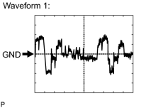
|
(e) Using an oscilloscope, check the waveform.
|
3. CHECK RADIO RECEIVER (for CD Changer Models)
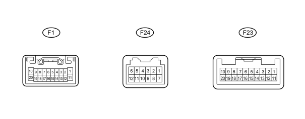
(a) Disconnect the F1 receiver connector.
(b) Measure the resistance and voltage according to the value(s) in the table below.
|
Terminal No. (Symbol) |
Wiring Color |
Terminal Description |
Condition |
Specified Condition |
|---|---|---|---|---|
|
F1-1 (B) - F1-20 (GND) |
L - BR |
Battery |
Always |
11 to 14 V |
|
F1-20 (GND) - Body ground |
BR - Body ground |
Ground |
Always |
Below 1 Ω |
|
F1-11 (ACC) - F1-20 (GND) |
GR - BR |
Accessory (ON) |
Engine switch off |
Below 1 V |
|
F1-11 (ACC) - F1-20 (GND) |
GR - BR |
Accessory (ON) |
Engine switch on (ACC) |
11 to 14 V |
If the result is not as specified, there may be a malfunction on the wire harness side.
(c) Reconnect the F1 receiver connector.
(d) Measure the voltage according to the value(s) in the table below.
|
Terminal No. (Symbol) |
Wiring Color |
Terminal Description |
Condition |
Specified Condition |
|---|---|---|---|---|
|
F1-2 (ILL+) - F1-20 (GND) |
G - BR |
Illumination signal |
Engine switch on (IG), light control switch off |
Below 1 V |
|
F1-2 (ILL+) - F1-20 (GND) |
G - BR |
Illumination signal |
Engine switch on (IG), light control switch tail or on |
11 to 14 V |
|
F1-7 (MUTE) - F1-20 (GND) |
B - BR |
Mute signal |
Audio system playing → changing modes |
3.5 V or higher → Below 1 V |
|
F1-8 (R+) - F1-20 (GND) |
B - BR |
Sound signal (right) |
Audio system playing |
Waveform synchronized with sound is output |
|
F1-9 (L+) - F1-20 (GND) |
R - BR |
Sound signal (left) |
Audio system playing |
Waveform synchronized with sound is output |
|
F1-18 (R-) - F1-20 (GND) |
W - BR |
Sound signal (right) |
Audio system playing |
Waveform synchronized with sound is output |
|
F1-19 (L-) - F1-20 (GND) |
G - BR |
Sound signal (left) |
Audio system playing |
Waveform synchronized with sound is output |
|
F1-12 (ILL- ) - F1-20 ( GND) |
W - BR |
Illumination signal |
Engine switch off |
Below 1 V |
|
F1-12 (ILL-) - F1-20 (GND) |
W - BR |
Illumination signal |
Engine switch on (IG) |
Pulse generation |
|
F1-5 (ATX+) - F1-20 (GND) |
R - BR |
AVC-LAN communication signal |
Engine switch on (ACC) |
2 to 3 V |
|
F1-15 (ATX-) - F1-20 (GND) |
W - BR |
AVC-LAN communication signal |
Engine switch on (ACC) |
2 to 3 V |
|
F23-9 (TX+) - F1-20 (GND) |
W - BR |
AVC-LAN communication signal |
Engine switch on (ACC) |
2 to 3 V |
|
F23-10 (TX-) - F1-20 (GND) |
L - BR |
AVC-LAN communication signal |
Engine switch on (ACC) |
2 to 3 V |
|
F24-9 (TXM+) - F1-20 (GND)* |
G - BR |
AVC-LAN communication signal |
Engine switch on (ACC) |
2 to 3 V |
|
F24-10 (TXM-) - F1-20 (GND)* |
R - BR |
AVC-LAN communication signal |
Engine switch on (ACC) |
2 to 3 V |
|
F1-13 (ANT) - F1-20 (GND) |
P - BR |
Power source of antenna |
Radio switch on and AM or FM |
11 to 14 V |
|
F23-6 (SWG) - F1-20 (GND) |
W - BR |
Steering pad switch ground |
Always |
Below 1 V |
|
F23-7 (SW1) - F1-20 (GND) |
L - BR |
Steering pad switch signal |
Steering pad switch not pushed |
4 V or higher |
|
F23-7 (SW1) - F1-20 (GND) |
L - BR |
Steering pad switch signal |
Steering pad switch seek+ switch pushed |
Below 2.5 V |
|
F23-7 (SW1) - F1-20 (GND) |
L - BR |
Steering pad switch signal |
Steering pad switch seek- switch pushed |
Below 0.9 V |
|
F23-7 (SW1) - F1-20 (GND) |
L - BR |
Steering pad switch signal |
Steering pad switch vol+ switch pushed |
Below 1.5 V |
|
F23-7 (SW1) - F1-20 (GND) |
L - BR |
Steering pad switch signal |
Steering pad switch vol+ switch pushed |
Below 0.9 V |
|
F23-8 (SW2) - F1-20 (GND) |
P - BR |
Steering pad switch signal |
Steering pad switch not pushed |
4 V or higher |
|
F23-8 (SW2) - F1-20 (GND) |
P - BR |
Steering pad switch signal |
Steering pad switch MODE switch pushed |
Below 2.5 V |
|
F23-8 (SW2) - F1-20 (GND) |
P - BR |
Steering pad switch signal |
Steering pad switch DISP switch pushed |
Below 2.5 V |
|
F23-15 (ARI) - F1-20 (GND) |
W - BR |
Sound signal (right) |
External device playing (When stereo jack used) |
Waveform synchronized with sound is output |
|
F23-16 (ASGW) - F1-20 (GND) |
R - BR |
Ground |
Always |
Below 1 V |
|
F23-18 (AGND) - F1-20 (GND) |
Shielded - Body ground |
Shielded ground |
Always |
Below 1 V |
|
F23-17 (ALI) - F1-20 (GND) |
B - BR |
Sound signal (left) |
External device playing (When stereo jack used) |
Waveform synchronized with sound is output |
|
F23-19 (AUXI) - F1-20 (GND) |
V - BR |
External device connection detection signal |
External device connected |
Below 1 V |
If the result is not as specified, the receiver may have a malfunction.
*: w/ SDARS System
4. CHECK STEREO COMPONENT AMPLIFIER (for DVD Changer Models)
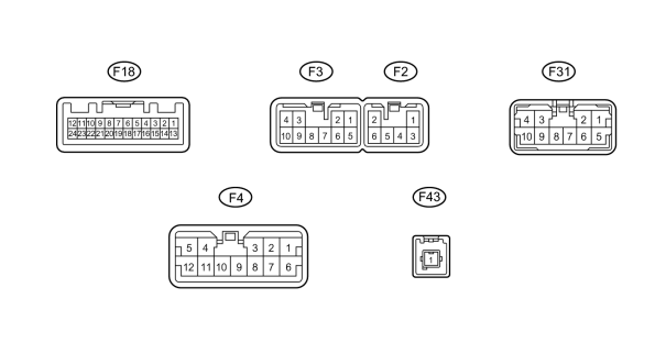
(a) Disconnect the F18 and F2 amplifier connectors.
(b) Measure the resistance and voltage according to the value(s) in the table below.
|
Terminal No. (Symbol) |
Wiring Color |
Terminal Description |
Condition |
Specified Condition |
|---|---|---|---|---|
|
F2-2 (GND) - Body ground |
W-B - Body ground |
Ground |
Always |
Below 1 Ω |
|
F2-6 (GND2) - Body ground |
W-B - Body ground |
Ground |
Always |
Below 1 Ω |
|
F2-1 (+B) - F2-2 (GND) |
L - W-B |
Battery |
Always |
11 to 14 V |
|
F2-3 (+B2) - F2-2 (GND) |
L - W-B |
Battery |
Always |
11 to 14 V |
|
F18-12 (ACC) - F2-2 (GND) |
GR - W-B |
Accessory (ON) |
Engine switch off |
Below 1 V |
|
F18-12 (ACC) - F2-2 (GND) |
GR - W-B |
Accessory (ON) |
Engine switch on (ACC) |
11 to 14 V |
If the result is not as specified, there may be a malfunction on the wire harness.
(c) Reconnect the F18 and F2 amplifier connectors.
(d) Measure the voltage according to the value(s) in the table below.
|
Terminal No. (Symbol) |
Wiring Color |
Terminal Description |
Condition |
Specified Condition |
|---|---|---|---|---|
|
F3-3 (CTR+) - F2-2 (GND) |
W - W-B |
Sound signal |
Audio system playing |
Waveform synchronized with sound is output |
|
F3-9 (CTR-) - F2-2 (GND) |
B - W-B |
Sound signal |
Audio system playing |
Waveform synchronized with sound is output |
|
F31-2 (FL+) - F2-2 (GND) |
W - W-B |
Sound signal |
Audio system playing |
Waveform synchronized with sound is output |
|
F31-6 (FL-) - F2-2 (GND) |
B - W-B |
Sound signal |
Audio system playing |
Waveform synchronized with sound is output |
|
F31-8 (FR+) - F2-2 (GND) |
W - W-B |
Sound signal |
Audio system playing |
Waveform synchronized with sound is output |
|
F31-7 (FR-) - F2-2 (GND) |
B - W-B |
Sound signal |
Audio system playing |
Waveform synchronized with sound is output |
|
F3-4 (RL+) - F2-2 (GND) |
B - W-B |
Sound signal |
Audio system playing |
Waveform synchronized with sound is output |
|
F3-10 (RL-) - F2-2 (GND) |
Y - W-B |
Sound signal |
Audio system playing |
Waveform synchronized with sound is output |
|
F31-1 (RR+) - F2-2 (GND) |
R - W-B |
Sound signal |
Audio system playing |
Waveform synchronized with sound is output |
|
F31-5 (RR-) - F2-2 (GND) |
W - W-B |
Sound signal |
Audio system playing |
Waveform synchronized with sound is output |
|
F3-1 (WF1+) - F2-2 (GND) |
W - W-B |
Sound signal |
Audio system playing |
Waveform synchronized with sound is output |
|
F3-6 (WF1-) - F2-2 (GND) |
B - W-B |
Sound signal |
Audio system playing |
Waveform synchronized with sound is output |
|
F18-15 (II1+) - F2-2 (GND) |
W - W-B |
Voice guidance signal |
Voice guidance playing |
Waveform synchronized with sound is output |
|
F18-14 (II1-) - F2-2 (GND) |
B - W-B |
Voice guidance signal |
Voice guidance playing |
Waveform synchronized with sound is output |
|
F18-11 (SPD) - F2-2 (GND) |
V - W-B |
Speed signal |
Engine switch on (IG), drive wheels turned slowly |
Pulse generation |
|
F18-1 (MUTE) - F2-2 (GND) |
B - W-B |
Mute signal |
Audio system playing → change mode |
3.5 V or higher → Below 1 V |
|
F18-24 (TMUT) - F2-2 (GND) |
B - W-B |
Mute signal |
Audio system playing → emergency call made |
3.5 V or higher → Below 1 V |
|
F18-8 (TX+) - F2-2 (GND) |
R - W-B |
AVC-LAN communication signal |
Engine switch on (ACC) |
2 to 3 V |
|
F18-7 (TX-) - F2-2 (GND) |
W - W-B |
AVC-LAN communication signal |
Engine switch on (ACC) |
2 to 3 V |
|
F18-5 (R+) - F2-2 (GND) |
B - W-B |
Sound signal (right) |
Audio system playing |
Waveform synchronized with sound is output |
|
F18-4 (R-) - F2-2 (GND) |
W - W-B |
Sound signal (right) |
Audio system playing |
Waveform synchronized with sound is output |
|
F18-3 (L+) - F2-2 (GND) |
R - W-B |
Sound signal (left) |
Audio system playing |
Waveform synchronized with sound is output |
|
F18-2 (L-) - F2-2 (GND) |
G - W-B |
Sound signal (left) |
Audio system playing |
Waveform synchronized with sound is output |
|
F31-3 (R-L+) - F2-2 (GND) |
W - W-B |
Sound signal (left) |
Audio system playing |
Waveform synchronized with sound is output |
|
F31-9 (R-L-) - F2-2 (GND) |
B - W-B |
Sound signal (left) |
Audio system playing |
Waveform synchronized with sound is output |
|
F31-4 (R-R+) - F2-2 (GND) |
W - W-B |
Sound signal (right) |
Audio system playing |
Waveform synchronized with sound is output |
|
F31-10 (R-R-) - F2-2 (GND) |
B - W-B |
Sound signal (right) |
Audio system playing |
Waveform synchronized with sound is output |
|
F4-2 (SL+) - F2-2 (GND) |
W - W-B |
Sound signal |
Audio system playing |
Waveform synchronized with sound is output |
|
F4-7 (SL-) - F2-2 (GND) |
B - W-B |
Sound signal |
Audio system playing |
Waveform synchronized with sound is output |
|
F4-1 (SR+) - F2-2 (GND) |
W - W-B |
Sound signal |
Audio system playing |
Waveform synchronized with sound is output |
|
F4-6 (SR-) - F2-2 (GND) |
B - W-B |
Sound signal |
Audio system playing |
Waveform synchronized with sound is output |
|
F4-10 (WFL+) - F2-2 (GND) |
P - W-B |
Sound signal |
Audio system playing |
Waveform synchronized with sound is output |
|
F4-8 (WFL-) - F2-2 (GND) |
V - W-B |
Sound signal |
Audio system playing |
Waveform synchronized with sound is output |
|
F4-5 (WFR+) - F2-2 (GND) |
LG - W-B |
Sound signal |
Audio system playing |
Waveform synchronized with sound is output |
|
F4-11 (WFR-) - F2-2 (GND) |
L - W-B |
Sound signal |
Audio system playing |
Waveform synchronized with sound is output |
|
F43-1 (DVD) - F2-2 (GND) |
# - W-B |
Digital image signal |
DVD played on radio receiver |
- |
If the result is not as specified, the amplifier may have a malfunction.
HINT:
#: There is no wire color information.
5. CHECK STEREO COMPONENT AMPLIFIER (for CD Changer Models)
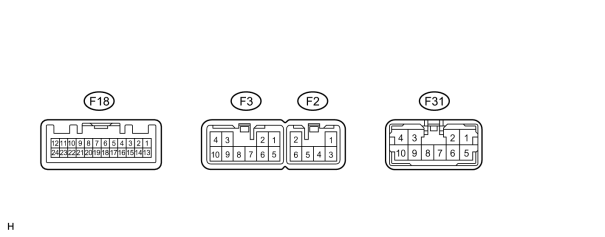
(a) Disconnect the F18 and F2 amplifier connectors.
(b) Measure the resistance and voltage according to the value(s) in the table below.
|
Terminal No. (Symbol) |
Wiring Color |
Terminal Description |
Condition |
Specified Condition |
|---|---|---|---|---|
|
F2-2 (GND) - Body ground |
W-B - Body ground |
Ground |
Always |
Below 1 Ω |
|
F2-6 (GND2) - Body ground |
W-B - Body ground |
Ground |
Always |
Below 1 Ω |
|
F2-1 (+B) - F2-2 (GND) |
L - W-B |
Battery |
Always |
11 to 14 V |
|
F18-12 (ACC) - F2-2 (GND) |
GR - W-B |
Accessory (ON) |
Engine switch off |
Below 1 V |
|
F18-12 (ACC) - F2-2 (GND) |
GR - W-B |
Accessory (ON) |
Engine switch on (ACC) |
11 to 14 V |
If the result is not as specified, there may be a malfunction on the wire harness.
(c) Reconnect the F18 and F2 amplifier connectors.
(d) Measure the voltage and waveform according to the value(s) in the table below.
|
Terminal No. (Symbol) |
Wiring Color |
Terminal Description |
Condition |
Specified Condition |
|---|---|---|---|---|
|
F3-3 (CTR+) - F2-2 (GND) |
W - W-B |
Sound signal |
Audio system playing |
Waveform synchronized with sound is output |
|
F3-9 (CTR-) - F2-2 (GND) |
B - W-B |
Sound signal |
Audio system playing |
Waveform synchronized with sound is output |
|
F31-2 (FL+) - F2-2 (GND) |
W - W-B |
Sound signal |
Audio system playing |
Waveform synchronized with sound is output |
|
F31-6 (FL-) - F2-2 (GND) |
B - W-B |
Sound signal |
Audio system playing |
Waveform synchronized with sound is output |
|
F31-8 (FR+) - F2-2 (GND) |
W - W-B |
Sound signal |
Audio system playing |
Waveform synchronized with sound is output |
|
F31-7 (FR-) - F2-2 (GND) |
B - W-B |
Sound signal |
Audio system playing |
Waveform synchronized with sound is output |
|
F18-3 (L+) - F2-2 (GND) |
R - W-B |
Sound signal |
Audio system playing |
Waveform synchronized with sound is output |
|
F18-2 (L-) - F2-2 (GND) |
G - W-B |
Sound signal |
Audio system playing |
Waveform synchronized with sound is output |
|
F18-5 (R+) - F2-2 (GND) |
B - W-B |
Sound signal |
Audio system playing |
Waveform synchronized with sound is output |
|
F18-4 (R-) - F2-2 (GND) |
W - W-B |
Sound signal |
Audio system playing |
Waveform synchronized with sound is output |
|
F18-11 (SPD) - F2-2 (GND) |
V - W-B |
Speed signal |
Engine switch on (IG), drive wheels turned slowly |
Pulse generation |
|
F18-1 (MUTE) - F2-2 (GND) |
B - W-B |
Mute signal |
Audio system playing → change mode |
3.5 V or higher → Below 1 V |
|
F18-8 (TX+) - F2-2 (GND) |
R - W-B |
AVC-LAN communication signal |
Engine switch on (ACC) |
2 to 3 V |
|
F18-7 (TX-) - F2-2 (GND) |
W - W-B |
AVC-LAN communication signal |
Engine switch on (ACC) |
2 to 3 V |
|
F18-5 (R+) - F2-2 (GND) |
B - W-B |
Sound signal (right) |
Audio system playing |
Waveform synchronized with sound is output |
|
F18-4 (R-) - F2-2 (GND) |
W - W-B |
Sound signal (right) |
Audio system playing |
Waveform synchronized with sound is output |
|
F18-3 (L+) - F2-2 (GND) |
R - W-B |
Sound signal (left) |
Audio system playing |
Waveform synchronized with sound is output |
|
F18-2 (L-) - F2-2 (GND) |
G - W-B |
Sound signal (left) |
Audio system playing |
Waveform synchronized with sound is output |
|
F31-3 (RL+) - F2-2 (GND) |
B - W-B |
Sound signal (left) |
Audio system playing |
Waveform synchronized with sound is output |
|
F31-9 (RL-) - F2-2 (GND) |
Y - W-B |
Sound signal (left) |
Audio system playing |
Waveform synchronized with sound is output |
|
F31-4 (RR+) - F2-2 (GND) |
R - W-B |
Sound signal (right) |
Audio system playing |
Waveform synchronized with sound is output |
|
F31-10 (RR-) - F2-2 (GND) |
W - W-B |
Sound signal (right) |
Audio system playing |
Waveform synchronized with sound is output |
|
F3-4 (WFL+) - F2-2 (GND) |
P - W-B |
Sound signal |
Audio system playing |
Waveform synchronized with sound is output |
|
F3-10 (WFL-) - F2-2 (GND) |
V - W-B |
Sound signal |
Audio system playing |
Waveform synchronized with sound is output |
|
F31-1 (WFR+) - F2-2 (GND) |
LG - W-B |
Sound signal |
Audio system playing |
Waveform synchronized with sound is output |
|
F31-5 (WFR-) - F2-2 (GND) |
L - W-B |
Sound signal |
Audio system playing |
Waveform synchronized with sound is output |
|
F18-15 (II1+) - F2-2 (GND) |
W - W-B |
Voice guidance signal |
Voice guidance provided |
Waveform synchronized with sound is output |
|
F18-14 (II1-) - F2-2 (GND) |
B - W-B |
Voice guidance signal |
Voice guidance provided |
Waveform synchronized with sound is output |
If the result is not as specified, the amplifier may have a malfunction.

|

|