| Last Modified: 11-27-2007 | 1.6 J | |
| Service Category: Audio/Visual/Telematics | Section: Navigation/Multi Info Display | |
| Model Year: 2008 | Model: LX570 | Doc ID: RM0000011F302CX |
| Title: NAVIGATION / MULTI INFO DISPLAY: NAVIGATION SYSTEM: DESCRIPTION (2008 LX570) | ||
|
Parking Brake Switch Circuit |
DESCRIPTION
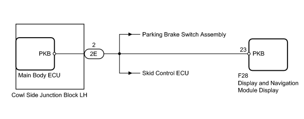
This circuit is from the parking brake switch to the display and navigation module display.
WIRING DIAGRAM
INSPECTION PROCEDURE
PROCEDURE
|
1. |
CHECK PARKING BRAKE (DISPLAY CHECK MODE) |
(a) Enter the "Display Check" mode and select "Parking Brake Signal Check"
 .
.
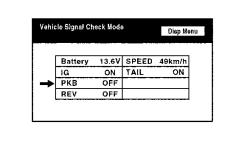
(b) Check that the display changes between ON and OFF according to the parking brake operation.
OK:
|
Parking Brake Position |
Display |
|---|---|
|
Applied |
ON |
|
Released |
OFF |
HINT:
This display is updated once per second. As a result, it is normal for the display to lag behind the actual change in the switch.
|

|
2. |
CHECK MAIN BODY ECU (PARKING BRAKE SIGNAL) |
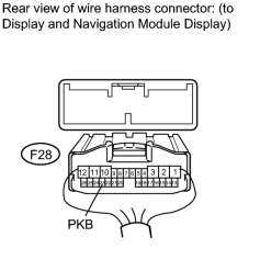
(a) Disconnect the F28 display connector.
|
(b) Measure the voltage according to the value(s) in the table below. Standard Voltage:
|
|
|
3. |
CHECK HARNESS AND CONNECTOR (DISPLAY AND NAVIGATION MODULE DISPLAY - MAIN BODY ECU) |
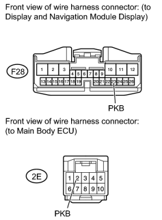
(a) Disconnect the F28 display connector.
(b) Disconnect the 2E ECU connector.
|
(c) Measure the resistance according to the value(s) in the table below. Standard Resistance:
|
|
|
4. |
REPLACE MAIN BODY ECU |
(a) Temporarily replace the ECU with a new or normally functioning one.
(b) Check that the parking brake signal is displayed on the multi-display.
OK:
Parking brake signal is displayed on the multi-display.
|

|

|