- Malfunction in the suspension control ECU.
- Open or short in the suspension control ECU circuit.
| Last Modified: 11-27-2007 | 1.6 C | |
| Service Category: Vehicle Exterior | Section: Lighting (ext) | |
| Model Year: 2008 | Model: LX570 | Doc ID: RM0000011SX00VX |
| Title: LIGHTING (EXT): LIGHTING SYSTEM: DESCRIPTION (2008 LX570) | ||
|
DTC |
B2416 |
Height Control Sensor Malfunction |
DESCRIPTION
The AFS ECU receives signals indicating the height of the vehicle from the suspension control ECU.
|
DTC Code |
DTC Detection Condition |
Trouble Area |
|---|---|---|
|
B2416 |
When either condition below is met: |
|
WIRING DIAGRAM
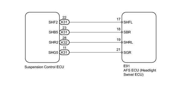
INSPECTION PROCEDURE
PROCEDURE
|
1. |
CHECK FOR DTC |
(a) Clear the DTCs
 .
.
(b) Check for DTCs
.
OK:
DTC B2416 output does not occur.
|

|
3. |
CHECK FOR DTC (AIR SUSPENSION SYSTEM) |
(a) Check for DTCs
.
OK:
DTC "C1712/12 Front Height Control Sensor LH Circuit Malfunction" and "C1714/14 Rear Height Control Sensor LH Circuit Malfunction" output does not occur.
|
|
4. |
READ VALUE USING TECHSTREAM (AFS ECU) |
(a) Using the Techstream, read the Data List.
AFS
|
Tester Display |
Measurement Item/Range |
Normal Condition |
Diagnostic Note |
|---|---|---|---|
|
Height Sens Pw Supply Val |
Height control sensor power supply value / Min.: 0 V, Max.: 5 V |
Power supply voltage to height control sensor |
- |
|
Fr Height Sens Signal Val |
Front height control sensor signal / Min.: 0 V, Max.: 5 V |
Height control sensor vehicle height value |
- |
|
Rr Height Sens Signal Val |
Rear height control sensor signal / Min.: 0 V, Max.: 5 V |
Height control sensor vehicle height value |
- |
OK:
Power supply voltage is approximately 5 V and height control sensor voltage changes when vehicle height is changed.
|
|
5. |
CHECK HARNESS AND CONNECTOR (AFS ECU - SUSPENSION CONTROL ECU) |
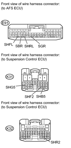
|
(a) Disconnect the E91, K31 and K32 ECU connectors. |
(b) Measure the resistance according to the value(s) in the table below.
Standard Resistance:
|
Tester Connection |
Condition |
Specified Condition |
|---|---|---|
|
E91-17 (SHFL) - K31-22 (SHF2) |
Always |
Below 1 Ω |
|
E91-18 (SBR) - K31-23 (SHB5) |
||
|
E91-19 (SHRL) - K32-28 (SHR2) |
||
|
E91-21 (SGR) - K31-11 (SHG5) |
||
|
E91-17 (SHFL) - Body ground |
Always |
10 kΩ or higher |
|
E91-18 (SBR) - Body ground |
||
|
E91-19 (SHRL) - Body ground |
||
|
E91-21 (SGR) - Body ground |
|
|
6. |
CHECK SUSPENSION CONTROL ECU |
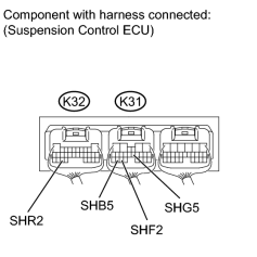
|
(a) Measure the voltage according to the value(s) in the table below. Standard Voltage:
|
(b) Measure the resistance according to the value(s) in the table below.
Standard Resistance:
|
Tester Connection |
Condition |
Specified Condition |
|---|---|---|
|
K31-11 (SHGS) - Body ground |
Always |
Below 1 Ω |
|

|

|