| Last Modified: 11-27-2007 | 1.6 J | |
| Service Category: Audio/Visual/Telematics | Section: Audio/Video | |
| Model Year: 2008 | Model: LX570 | Doc ID: RM0000019NG05EX |
| Title: AUDIO / VIDEO: AUDIO AND VISUAL SYSTEM: DESCRIPTION (2008 LX570) | ||
|
AVC-LAN Circuit |
DESCRIPTION
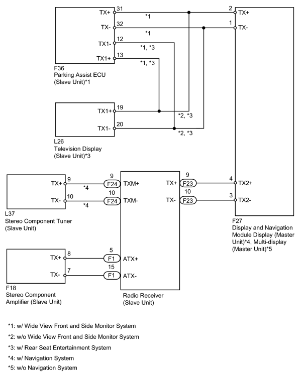
Each unit of the navigation system connected to the AVC-LAN (communication bus) communicates by transferring the signals from each switch.
When a short to +B or short to ground occurs in the AVC-LAN, the navigation system will not function normally as communication is discontinued.
WIRING DIAGRAM
INSPECTION PROCEDURE
PROCEDURE
|
1. |
CHECK RADIO RECEIVER ASSEMBLY |
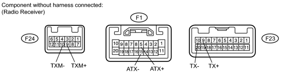
(a) Disconnect the F1, F23 and F24 receiver connectors.
(b) Measure the resistance according to the value(s) in the table below.
Standard Resistance:
|
Tester Connection |
Condition |
Specified Condition |
|---|---|---|
|
F1-5 (ATX+) - F1-15 (ATX-) |
Always |
60 to 80 Ω |
|
F23-9 (TX+) - F23-10 (TX-) |
Always |
60 to 80 Ω |
|
F24-9 (TXM+) - F24-10 (TXM-) |
Always |
60 to 80 Ω |
|

|
2. |
CHECK HARNESS AND CONNECTOR |
HINT:
For details of the connectors, refer to Terminals of ECU
 .
.
(a) Referring to the AVC-LAN wiring diagram, check all AVC-LAN circuits.
(1) Disconnect all connectors in all AVC-LAN circuits.
(2) Check for an open or short in all AVC-LAN circuits.
OK:
There is no open or short circuit.
|

|

|