| Last Modified: 11-27-2007 | 1.6 A | |
| Service Category: Brake | Section: Brake Control/Dynamic Control System | |
| Model Year: 2008 | Model: LX570 | Doc ID: RM000001B2H00CX |
| Title: BRAKE CONTROL / DYNAMIC CONTROL SYSTEMS: FRONT SPEED SENSOR: INSTALLATION (2008 LX570) | ||
INSTALLATION
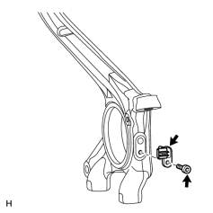
1. INSTALL FRONT SPEED SENSOR LH
|
(a) Using a 5 mm hexagon wrench, install the speed sensor with the bolt. Torque: 8.3 N·m (85 kgf·cm, 73 in·lbf) NOTICE:
|
2. INSTALL FRONT SKID CONTROL SENSOR WIRE LH

|
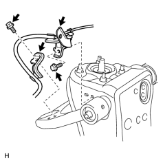
(a) Connect the 2 connectors. |
(b) Install the harness clamp with the bolt.
Torque: 13 N·m (127 kgf·cm, 9 ft·lbf)
NOTICE:
- When installing the clamp, do not twist the wire harness.
- Make sure the clamp rotation stopper touches the installation position.
|
(c) Install the 2 harness clamps with the 2 bolts. Torque: 13 N·m (127 kgf·cm, 9 ft·lbf) NOTICE:
|
|
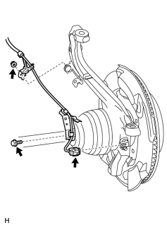
(d) Install the harness clamp with the nut. Torque: 13 N·m (127 kgf·cm, 9 ft·lbf) NOTICE:
|
|
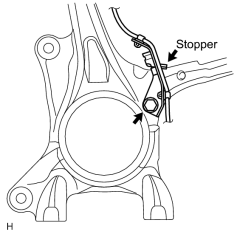
(e) Install the harness clamp with the bolt. Torque: 13 N·m (127 kgf·cm, 9 ft·lbf) NOTICE:
Install the bracket so that the rotation stopper touches the knuckle. |
(f) Connect the speed sensor connector.
NOTICE:
Securely connect the connector.
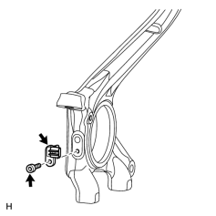
3. INSTALL FRONT SPEED SENSOR RH
|
(a) Using a 5 mm hexagon wrench, install the speed sensor with the bolt. Torque: 8.3 N·m (85 kgf·cm, 73 in·lbf) NOTICE:
|
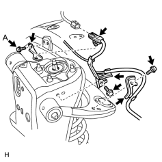
4. INSTALL FRONT SKID CONTROL SENSOR WIRE RH
|
(a) Install the skid control sensor clamp with the bolt (labeled A). Torque: 5.0 N·m (51 kgf·cm, 44 in·lbf) |
(b) Attach the connector to the skid control sensor clamp and then connect the connector.
(c) Install the 2 harness clamps with the 2 bolts.
Torque: 13 N·m (127 kgf·cm, 9 ft·lbf)
NOTICE:
- When installing the clamps, do not twist the wire harness.
- Make sure the clamp rotation stopper touches the installation position.
|
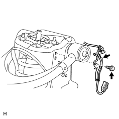
(d) Install the harness clamp with the bolt. Torque: 13 N·m (127 kgf·cm, 9 ft·lbf) |
(e) Connect the connector.
|
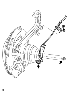
(f) Install the harness clamp with the nut. Torque: 13 N·m (127 kgf·cm, 9 ft·lbf) NOTICE:
|
|
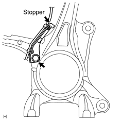
(g) Install the harness clamp with the bolt. Torque: 13 N·m (127 kgf·cm, 9 ft·lbf) NOTICE:
Install the bracket so that the rotation stopper touches the knuckle. |
(h) Connect the speed sensor connector.
NOTICE:
Securely connect the connector.
5. INSTALL FRONT WHEEL
Torque: 131 N·m (1336 kgf·cm, 97 ft·lbf)
6. CONNECT CABLE TO NEGATIVE BATTERY TERMINAL
NOTICE:
When disconnecting the cable, some systems need to be initialized after the cable is reconnected
 .
.
7. CHECK SPEED SENSOR SIGNAL
(a) Check the speed sensor signal
.

|

|