- Front speed sensor RH
- Sensor installation
- Speed sensor rotor
| Last Modified: 11-27-2007 | 1.6 D | |
| Service Category: Brake | Section: Brake Control/Dynamic Control System | |
| Model Year: 2008 | Model: LX570 | Doc ID: RM00000252H00CX |
| Title: BRAKE CONTROL / DYNAMIC CONTROL SYSTEMS: VEHICLE STABILITY CONTROL SYSTEM: TEST MODE PROCEDURE (2008 LX570) | ||
TEST MODE PROCEDURE
1. TEST MODE (SIGNAL CHECK) PROCEDURE (SST CHECK WIRE)
HINT:
-
After replacing the master cylinder solenoid and/or yaw rate and G sensor or performing a vehicle height adjustment, make sure to perform yaw rate and G sensor zero point calibration
 .
.
- If the engine switch is turned from on (IG) to on (ACC) or off during test mode (signal check), DTCs of the signal check function will be cleared.
- During test mode (signal check), the skid control ECU stores all DTCs of the test mode (signal check) function. By performing the test mode (signal check), the codes are cleared if normality is confirmed. The codes left over are the codes where an abnormality was found.
(a) Turn the engine switch off.
(b) Check that the steering wheel is centered and move the shift lever to P.
|
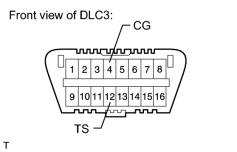
(c) Using SST, connect terminals 12 (TS) and 4 (CG) of the DLC3. SST: 09843-18040 |
(d) Turn the engine switch on (IG).
|
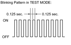
(e) Check that "VSC TEST MODE" is displayed on the multi-information display and check that the ABS warning light blinks in test mode. HINT:
|
(f) Start the engine.
(g) Using a check wire, perform the ABS sensor (G sensor, stop light switch, master cylinder pressure sensor, center differential lock detection switch and speed sensor) and VSC sensor (yaw rate sensor and CRAWL switch) signal checks in test mode (ABS sensor: See procedure "A" to "F", VSC sensor: See procedure "G" to "J").
2. G SENSOR SIGNAL CHECK (SST CHECK WIRE) (Procedure "A")
|
|
(a) Check that the ABS warning light is blinking in test mode. |
(b) Keep the vehicle stationary on a level surface for 2 seconds or more.
3. STOP LIGHT SWITCH SIGNAL CHECK (SST CHECK WIRE) (Procedure "B")
(a) Park the vehicle and move the shift lever to P.
(b) After releasing the brake pedal for 1 second or more, depress the brake pedal with a force of 50 N (5 kgf, 11.2 lbf) or more and check that the skid control buzzer sounds for 3 seconds.
CAUTION:
Be careful as the brake pedal cannot be depressed as far as it can under normal operation.
HINT:
The master cylinder pressure sensor signal check in the next step may finish at the same time as this check.
4. MASTER CYLINDER PRESSURE SENSOR SIGNAL CHECK (SST CHECK WIRE) (Procedure "C")
|
|
(a) Check that the ABS warning light is blinking in test mode. |
(b) Leave the vehicle in a stationary condition and release the brake pedal for 1 second or more, and then quickly depress the brake pedal with a force of 98 N (10 kgf, 22.0 lbf) or more for 1 second or more.
HINT:
- At this time, the ABS warning light stays on for 3 seconds.
- The ABS warning light comes on for 3 seconds every time the brake pedal operation above is performed.
5. CENTER DIFFERENTIAL LOCK DETECTION SWITCH SIGNAL CHECK (SST CHECK WIRE) (Procedure "D")
|
|
(a) Check that the ABS warning light is blinking in test mode. |
(b) Check the center differential lock switch.
(1) Push the center differential lock switch on to lock the center differential.
(2) Push the center differential lock switch off to unlock the center differential.
6. SPEED SENSOR SIGNAL CHECK (SST CHECK WIRE) (Procedure "E")
|
|
(a) Check that the ABS warning light is blinking in test mode. |
(b) Check the reverse signal.
(1) Drive the vehicle in reverse for more than 1 second at 3 km/h (2 mph) or more.
HINT:
Drive the vehicle in reverse and check the speed sensor signal. Note that the signal check cannot be completed if the vehicle speed is 45 km/h (28 mph) or more.
(c) Check the forward signal.
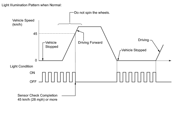
(1) Drive the vehicle straight forward.
Drive the vehicle at a speed of 45 km/h (28 mph) or more for several seconds and check that the ABS warning light goes off.
NOTICE:
The signal check may not be completed if the vehicle has its wheels spun or the steering wheel is turned during this check.
(d) Stop the vehicle.
NOTICE:
- The speed sensor signal check may not be completed if the speed sensor signal check is started while turning the steering wheel or spinning the wheels.
- If the signal check has not been completed, the ABS warning light blinks while driving and the ABS system does not operate.
HINT:
When the signal check has been completed, the ABS warning light goes off while driving and blinks in the test mode pattern while stationary.
7. READ DTC OF ABS SENSOR (SST CHECK WIRE) (Procedure "F")
|
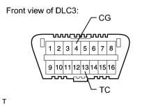
(a) Using SST, connect terminals 13 (TC) and 4 (CG) of the DLC3. SST: 09843-18040 |
(b) Read the number of blinks of the ABS warning light.
HINT:
- See the list of DTCs (See procedure "I").
- If every sensor is normal, the normal system code is output (a cycle of 0.25 seconds on and 0.25 seconds off is repeated).
- If more than 1 malfunction is detected at the same time, the lowest numbered code will be output first.
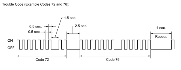
(c) After the check, disconnect SST from terminals 13 (TC) and 4 (CG) of the DLC3.
8. CRAWL SWITCH SIGNAL CHECK (SST CHECK WIRE) (Procedure "G")
(a) Check that "VSC TEST MODE" is displayed on the multi-information display.
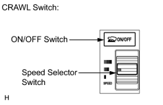
|
(b) Check the CRAWL switch. (1) Turn the ON/OFF switch on. (2) Turn the ON/OFF switch off. (3) Turn the speed selector switch to low. (4) Turn the speed selector switch to middle. (5) Turn the speed selector switch to high. (6) Turn the speed selector switch to low. |
9. YAW RATE SENSOR SIGNAL CHECK (SST CHECK WIRE) (Procedure "H")
(a) Check that "VSC TEST MODE" is displayed on the multi-information display.
(b) Check the zero point voltage of the yaw rate sensor.
(1) Keep the vehicle stationary on a level surface for 1 second or more.
(c) Check the output of the yaw rate sensor and the direction of the steering angle sensor.
|
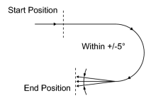
(1) Move the shift lever to D and drive the vehicle at a vehicle speed of 5 km/h (3 mph) or more, and then turn the steering wheel either to the left or right 90° or more until the vehicle makes a 180° turn. |
(2) Stop the vehicle and move the shift lever to P. Check that the skid control buzzer sounds for 3 seconds.
HINT:
- If the skid control buzzer sounds, the signal check has completed normally.
-
If the skid control buzzer does not sound, check the skid control buzzer circuit
, then perform the signal check again.
- If the skid control buzzer still does not sound, there is a malfunction in the yaw rate sensor, so check the DTC.
- Drive the vehicle in a 180° circle. At the end of the turn, the direction of the vehicle should be within 175 to 185° of its start position.
- Do not spin the wheels.
10. READ DTC OF VSC SENSOR (SST CHECK WIRE) (Procedure "I")
|
|
(a) Using SST, connect terminals 13 (TC) and 4 (CG) of the DLC3. SST: 09843-18040 |
(b) Read the codes output on the multi-information display.
HINT:
- See the list of DTCs (See procedure "I").
- If every sensor/switch is normal, "DIAG VSC OK" is displayed on the multi-information display.
- If more than 1 malfunction is detected at the same time, the lowest numbered code will be output first.
(c) After performing the check, turn the engine switch off and disconnect SST from terminals 13 (TC) and 4 (CG) of the DLC3.
(d) Turn the engine switch on (IG).
11. DTC OF SIGNAL CHECK FUNCTION (SST CHECK WIRE) (Procedure "J")
ABS Sensor
|
DTC Code |
Detection Item |
Trouble Area |
|---|---|---|
|
C1271/71 |
Front Speed Sensor RH Output Voltage Malfunction |
|
|
C1272/72 |
Front Speed Sensor LH Output Voltage Malfunction |
|
|
C1273/73 |
Rear Speed Sensor RH Output Voltage Malfunction |
|
|
C1274/74 |
Rear Speed Sensor LH Output Voltage Malfunction |
|
|
C1275/75 |
Abnormal Change in Output Signal of Front Speed Sensor RH |
Speed sensor rotor |
|
C1276/76 |
Abnormal Change in Output Signal of Front Speed Sensor LH |
Speed sensor rotor |
|
C1277/77 |
Abnormal Change in Output Signal of Rear Speed Sensor RH |
Speed sensor rotor |
|
C1278/78 |
Abnormal Change in Output Signal of Rear Speed Sensor LH |
Speed sensor rotor |
|
C1279/79 |
G Sensor Output Voltage Malfunction |
|
|
C1281/81 |
Master Cylinder Pressure Sensor Output Malfunction |
|
|
C1282/82 |
Center Differential Lock Detection Switch Malfunction |
Center differential lock switch |
VSC Sensor
|
DTC Code |
Detection Item |
Trouble Area |
|---|---|---|
|
C0371/71 |
Yaw Rate Sensor Malfunction |
Yaw rate and G sensor |
|
C1379/74 |
CRAWL Switch Malfunction |
CRAWL switch |
HINT:
The codes in this table are stored only in test mode (signal check).
12. TEST MODE (SIGNAL CHECK) PROCEDURE (TECHSTREAM)
HINT:
-
After replacing the master cylinder solenoid and/or yaw rate and G sensor or performing a vehicle height adjustment, make sure to perform yaw rate and G sensor zero point calibration
.
- If the engine switch is turned from on (IG) to on (ACC) or off during test mode (signal check), DTCs of the signal check function will be cleared.
- During test mode (signal check), the skid control ECU stores all DTCs of the test mode (signal check) function. By performing the test mode (signal check), the codes are cleared if normality is confirmed. The codes left over are the codes where an abnormality was found.
(a) Turn the engine switch off.
(b) Check that the steering wheel is centered and move the shift lever to P.
(c) Connect the Techstream to the DLC3.
(d) Turn the engine switch on (IG).
(e) Turn the Techstream on.
(f) Enter the following menus: Chassis / ABS/VSC/TRAC / Utility / Signal Check.
|
|
(g) Check that "VSC TEST MODE" is displayed on the multi-information display and check that the ABS warning light blinks in test mode. HINT:
|
(h) Start the engine.
(i) Using the Techstream, perform the ABS sensor (G sensor, stop light switch, master cylinder pressure sensor, center differential lock detection switch and speed sensor) and VSC sensor (yaw rate sensor and CRAWL switch) signal checks in test mode (ABS sensor: See procedure "K" to "P", VSC sensor: See procedure "Q" to "S").
13. G SENSOR SIGNAL CHECK (TECHSTREAM) (Procedure "K")
|
|
(a) Check that the ABS warning light is blinking in test mode. |
(b) Keep the vehicle stationary on a level surface for 2 seconds or more.
14. STOP LIGHT SWITCH SIGNAL CHECK (TECHSTREAM) (Procedure "L")
(a) Park the vehicle and move the shift lever to P.
(b) After releasing the brake pedal for 1 second or more, depress the brake pedal with a force of 50 N (5 kgf, 11.2 lbf) or more and check that the skid control buzzer sounds for 3 seconds.
CAUTION:
Be careful as the brake pedal cannot be depressed as far as it can under normal operation.
HINT:
The master cylinder pressure sensor signal check in the next step may finish at the same time as this check.
15. MASTER CYLINDER PRESSURE SENSOR SIGNAL CHECK (TECHSTREAM) (Procedure "M")
|
|
(a) Check that the ABS warning light is blinking in test mode. |
(b) Leave the vehicle in a stationary condition and release the brake pedal for 1 second or more, and then quickly depress the brake pedal with a force of 98 N (10 kgf, 22 lbf) or more for 1 second or more.
HINT:
- At this time, the ABS warning light stays on for 3 seconds.
- The ABS warning light comes on for 3 seconds every time the brake pedal operation above is performed.
16. CENTER DIFFERENTIAL LOCK DETECTION SWITCH SIGNAL CHECK (TECHSTREAM) (Procedure "N")
|
|
(a) Check that the ABS warning light is blinking in test mode. |
(b) Check the center differential lock switch.
(1) Push the center differential lock switch on to lock the center differential.
(2) Push the center differential lock switch off to unlock the center differential.
17. SPEED SENSOR SIGNAL CHECK (TECHSTREAM) (Procedure "O")
|
|
(a) Check that the ABS warning light is blinking in test mode. |
(b) Check the reverse signal.
(1) Drive the vehicle in reverse for more than 1 second at 3 km/h (2 mph) or more.
HINT:
Drive the vehicle in reverse and check the speed sensor signal. Note that the signal check cannot be completed if the vehicle speed is 45 km/h (28 mph) or more.
(c) Check the forward signal.
(1) Drive the vehicle straight forward. Drive the vehicle at a speed of 45 km/h (28 mph) or more and check that the ABS warning light goes off.
NOTICE:
The signal check may not be completed if the vehicle has its wheels spun or the steering wheel is turned during this check.
(d) Stop the vehicle.
NOTICE:
- The speed sensor signal check may not be completed if the speed sensor signal check is started while turning the steering wheel or spinning the wheels.
- If the signal check has not been completed, the ABS warning light blinks while driving and the ABS system does not operate.
HINT:
When the signal check has been completed, the ABS warning light goes off while driving and blinks in the test mode pattern while stationary.
18. READ DTC OF ABS SENSOR (TECHSTREAM) (Procedure "P")
(a) Read the DTC(s) by following the Techstream screen.
HINT:
- Refer to the Techstream operator's manual for further details.
- See the list of DTCs (See procedure "T").
19. CRAWL SWITCH SIGNAL CHECK (TECHSTREAM) (Procedure "Q")
(a) Check that "VSC TEST MODE" is displayed on the multi-information display.
|
|
(b) Check the CRAWL switch. (1) Turn the ON/OFF switch on. (2) Turn the ON/OFF switch off. (3) Turn the speed selector switch to low. (4) Turn the speed selector switch to middle. (5) Turn the speed selector switch to high. (6) Turn the speed selector switch to low. |
20. YAW RATE SENSOR SIGNAL CHECK (TECHSTREAM) (Procedure "R")
(a) Check that "VSC TEST MODE" is displayed on the multi-information display.
(b) Check the zero point voltage of the yaw rate sensor.
(1) Keep the vehicle stationary on a level surface for 1 second or more.
(c) Check the output of the yaw rate sensor and the direction of the steering angle sensor.
|
|
(1) Move the shift lever to D and drive the vehicle at a vehicle speed of 5 km/h (3 mph) or more, and then turn the steering wheel either to the left or right 90° or more until the vehicle makes a 180° turn. |
(2) Stop the vehicle and move the shift lever to P. Check that the skid control buzzer sounds for 3 seconds.
HINT:
- If the skid control buzzer sounds, the signal check has completed normally.
-
If the skid control buzzer does not sound, check the skid control buzzer circuit
, then perform the signal check again.
- If the skid control buzzer still does not sound, there is a malfunction in the yaw rate sensor, so check the DTC.
- Drive the vehicle in a 180° circle. At the end of the turn, the direction of the vehicle should be within 175° to 185° of its start position.
- Do not spin the wheels.
21. READ DTC OF VSC SENSOR (TECHSTREAM) (Procedure "S")
(a) Read the DTC(s) by following the Techstream screen.
HINT:
- Refer to the Techstream operator's manual for further details.
- See the list of DTCs (See procedure "R").
22. DTC OF SIGNAL CHECK FUNCTION (TECHSTREAM) (Procedure "T")
ABS Sensor
|
DTC Code |
Detection Item |
Trouble Area |
|---|---|---|
|
C1271/71 |
Front Speed Sensor RH Output Voltage Malfunction |
|
|
C1272/72 |
Front Speed Sensor LH Output Voltage Malfunction |
|
|
C1273/73 |
Rear Speed Sensor RH Output Voltage Malfunction |
|
|
C1274/74 |
Rear Speed Sensor LH Output Voltage Malfunction |
|
|
C1275/75 |
Abnormal Change in Output Signal of Front Speed Sensor RH |
Speed sensor rotor |
|
C1276/76 |
Abnormal Change in Output Signal of Front Speed Sensor LH |
Speed sensor rotor |
|
C1277/77 |
Abnormal Change in Output Signal of Rear Speed Sensor RH |
Speed sensor rotor |
|
C1278/78 |
Abnormal Change in Output Signal of Rear Speed Sensor LH |
Speed sensor rotor |
|
C1279/79 |
G Sensor Output Voltage Malfunction |
|
|
C1281/81 |
Master Cylinder Pressure Sensor Output Malfunction |
|
|
C1282/82 |
Center Differential Lock Detection Switch Malfunction |
Center differential lock switch |
VSC Sensor
|
DTC Code |
Detection Item |
Trouble Area |
|---|---|---|
|
C0371/71 |
Yaw Rate Sensor Malfunction |
Yaw rate and G sensor |
|
C1379/74 |
CRAWL Switch Malfunction |
CRAWL switch |
HINT:
The codes in this table are stored only in test mode (signal check).

|

|