- When detecting an abnormal signal from the fluid temperature sensor (fluid temperature sensor terminal voltage of ECU is 0.1 V or less or 4.8 V or higher) for 1 second.
- When there is a fluid temperature sensor power supply voltage malfunction.
| Last Modified: 11-27-2007 | 1.6 C | |
| Service Category: Suspension | Section: Suspension Control System | |
| Model Year: 2008 | Model: LX570 | Doc ID: RM000001CU5006X |
| Title: SUSPENSION CONTROL: ACTIVE HEIGHT CONTROL SUSPENSION: DESCRIPTION (2008 LX570) | ||
|
DTC |
C1719 |
Oil Temperature Sensor Circuit Malfunction |
DESCRIPTION
This circuit is used for sending the data to detect the fluid temperature of the pump. The abnormality of the fluid is judged by the ECU.
|
DTC Code |
Detection Condition |
Trouble Area |
|---|---|---|
|
C1719 |
When one of the following conditions is met: |
|
WIRING DIAGRAM
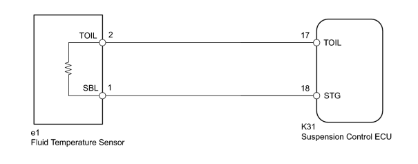
INSPECTION PROCEDURE
NOTICE:
- Before performing troubleshooting, inspect the connectors of related circuits.
-
If the suspension control ECU or height control sensor is replaced, the vehicle height offset calibration must be performed
 .
.
PROCEDURE
|
1. |
READ VALUE USING TECHSTREAM (OIL TEMPERATURE SENSOR) |
(a) Turn the engine switch off.
(b) Connect the Techstream to the DLC3.
(c) Turn the engine switch on (IG) and the Techstream on.
(d) Enter the following menus: Chassis / AHC / Data List.
(e) According to the display on the Techstream, read the Data List.
AHC
|
Tester Display |
Measurement Item/Range |
Normal Condition |
Diagnostic Note |
|---|---|---|---|
|
Oil Temperature Sensor |
Fluid temperature sensor reading / min.: -3276.8°C (-5866.24°F) max.: 3276.7°C (5930.06°F) |
Actual fluid temperature |
- |
OK:
Same as actual fluid temperature
|

|
2. |
RECONFIRM DTC OUTPUT |
(a) Clear the DTCs
.
(b) Perform a road test.
(c) Check for DTCs.
Result
|
Result |
Proceed to |
|---|---|
|
DTC C1719 is output |
A |
|
DTC C1719 is not output |
B |
|
|
3. |
CHECK HARNESS AND CONNECTOR (TEMPERATURE SENSOR - SUSPENSION CONTROL ECU) |
NOTICE:
When inspecting the wire harness between the suspension control ECU and temperature sensor, it is difficult to determine the malfunctioning area if there is a sensor power supply malfunction. Therefore, disconnect the connectors for the temperature sensor, the acceleration sensors (front RH, front LH) and pressure accumulator sensor on the ECU side.
(a) Disconnect the K30 and K31 ECU connectors.
(b) Disconnect the e1 sensor connector.
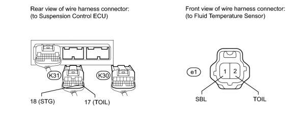
(c) Measure the resistance according to the value(s) in the table below.
Standard Resistance:
|
Tester Connection |
Condition |
Specified Condition |
|---|---|---|
|
K31-17 (TOIL) - e1-2 (TOIL) |
Always |
Below 1 Ω |
|
K31-17 (TOIL) - Body ground |
Always |
10 kΩ or higher |
|
K31-18 (STG) - e1-1 (SBL) |
Always |
Below 1 Ω |
|
K31-18 (STG) - Body ground |
Always |
10 kΩ or higher |
|
|
4. |
INSPECT FLUID TEMPERATURE SENSOR |
(a) Connect the e1 temperature sensor connector.
(b) Disconnect the K30 and K31 ECU connectors.
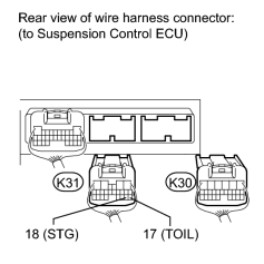
(c) Measure the resistance according to the value(s) in the table below.
Standard Resistance:
|
Tester Connection |
Condition |
Specified Condition |
|---|---|---|
|
K31-17 (TOIL) - K31-18 (STG) |
20°C (68°F) |
2.32 to 2.59 kΩ |
|

|

|